How to Build a Cheap Thermometer and IR Blaster For Home Assistant
Updated on 15th Sep 2020 23:25 in DIY, Home Assistant, Tutorial
The situation seems so familiar: you have an air conditioner unit that uses an IR remote, but you want to control it via your own thermostat. At least then you could manage it remotely or start cooling the air before you get home from work. This was the situation I was in, and to solve it, I built a Home Assistant temperature sensor with an onboard IR blaster, allowing it to also send commands to my portable air conditioner. All of this can be done for under 20$ as a relatively simple DIY project.
Disclaimer: This post contains affiliate links. As an Amazon Associate, I earn from qualifying purchases.
Table of Contents
Bill of materials
For materials, there are two major components we will specify separately. Those are the circuit, which is a list of the necessary parts for this project to work and the case, which is just a way to hide the circuit and wires in a nice little box. Feel free to only build the circuit and use something else to contain the circuits (or just a piece of paper under the perf board to stop the pins from shorting, like I did for a while).
The circuit
- An ESP8266, NodeMCU style
- A DHT22 sensor unit
- IR LED, can be bought in a pack like this
- 1x 2.2k resistor, if you need these, it might be better to get an assorted pack
- 1x 50ohm resistor - if you can't find a 50 ohm, you can probably get away with as low as a 35ohm.
- NPN transistor
- A piece of perf board, I used the 5cm X 7cm size from the linked kit
The case
- 3D printer
- PLA filament
The case will be 3D printed, the method for doing this is beyond the scope of this article, but we will provide STL files and a quick overview of the recommended settings.
The build
To build the circuit, simply follow the schematic below:
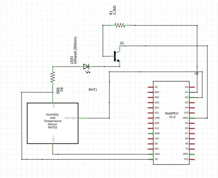
The ESP pins used in the schematic are critical because they will be used as shown in the diagram in the code - so don't change them unless you know what you are doing. Additionally, some other pins could cause problems with either the LED or the sensor, so stick to these for the best results. Note: some boards have misprinted labels on the PCB, just ensure that you connect the right thing to the right place by comparing your ESP to the diagram.
The IR LED is driven by pin D1 via a transistor. The reason this is needed is that the ESP is not designed to provide currents above 12mA, so connecting the LED directly will either result in a very dim IR light that will be hard to diagnose or the ESP getting very hot and potentially dying. There is also a current limiting resistor between the LED and Vcc to keep the current well below its maximum rating.
We put a 2.2k resistor between the D1 and the transistor, which again limits the current into the transistor but has the vital role of ensuring the current is high enough for the transistor to enter saturation mode. The theory is relatively long, but if it interests you, this is an excellent guide on how this works.
When it comes to the DHT22, it makes use of a special one-wire protocol to communicate both the temperature and humidity to the ESP. Unfortunately, this protocol is custom and not the easiest to interface with. In the code, we will make use of a library for reading from these sensors to avoid having to deal with it.
I recommend building everything on a breadboard first, then once you confirm that everything works as expected, you can move it to a more permanent perf board. Once everything is assembled, you will have the electrical aspect of the thermostat ready. Now you can either leave it on the perf board or 3D print an enclosure for the device.
Building a case
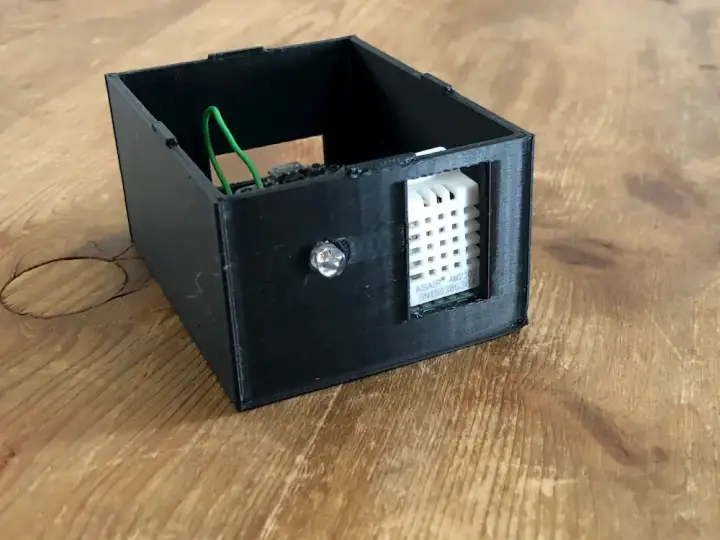
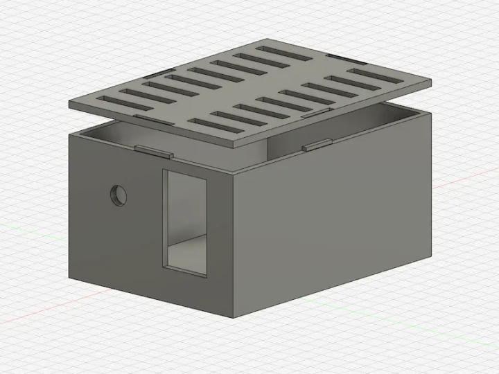
If you choose to build a case, download the following STL files: lid.stl and case.stl. Import them into your slicer of choice, set 10% infill, and supports on. I recommend printing at lower speeds, around 50ms-60ms for the best results. I had a lot of problems at higher speeds for some reason, so keep that in mind. The design is nothing too fancy and contains cutouts for the temperature sensor, IR LED, and the USB port on the back of the ESP.
Feel free to modify the STL files to whatever you like! I wanted to keep things simple, but you can get as creative as you like at this stage, just remember to consider the angle of the IR LED in your final installation. One important thing to consider, which I missed originally, is that the ESP8266 outputs quite a lot of heat. The lid includes vent holes that are designed to allow the heat within the case to quickly escape, instead of falsely increasing the temperature readings.
The software
Inspired by both the Losant IoT DHT22 example and the ESP8266WebServer core library examples, the code will periodically fetch the sensor value and save it in memory. When requested via HTTP, it will then provide this saved value in the body of the response as a JSON object. The code involves quite a few moving parts, so we will cover each important element one at a time.
ESP8266 support for the Arduino IDE
I use the Arduino IDE to develop applications for the ESP. It is straightforward to do, simply follow the instructions found on the ESP Arduino Github to install the tools via the board manager. Once that's done, you will be able to select the ESP as a board from the "Tools->Board:->ESP8266 Boards->NodeMCU v1.0", assuming you are using the same ESP board from the BoM.
A quick note on security
As the code currently stands, there is no mechanism for verifying who is issuing requests to the system. Do not use this on an unsecured network, with the risk of someone being able to access the device. If you want to make things more secure, adding an authorization header would already make things much better, but this is outside the scope of this article. This code is considered okay to use for testing and maybe situations where controlling access is not important, such as a small private network.
Downloading the required libraries
The code makes use of quite a few libraries that are all crucial to the proper function of the project. With the Arduino IDE open, head over to the "Sketch->Include Library->Manage Libraries" menu. The library manager will open, allowing you to search for the libraries to install. Be sure to select the version listed beside the name of the library to ensure it will work with the code.
Required libraries:
- IRremoteESP8266 @ v2.6.4
- DHT sensor library @ v1.3.0
- ArduinoJson @ v6.11
Ensure all of these are installed before attempting to compile. Also, ensure that the ESP board is selected under the "Tools->Board:" menu, as this project makes use of many of the core libraries that are only included if you select the correct board.
Modifying the variables
There are a few different variables that need to be changed for the code to work in your environment. The variables that will need changing are SSID and pass, IP addresses, and the IRTc1112Ac class.
Set the SSID and pass variables to be both the name of your WiFi network and the password to the network, respectively. Also, change the IP addresses to match your local network configuration.
Finally, modify the IRTc1112Ac class of the "toshibair" variable to match the one on your air conditioner. This is the part that will take some experimenting, as unfortunately, each A/C will be using different IR codes. It is sometimes not obvious which one you should use, which is why I recommend trying a few if you aren't sure. In my case, a "TCL" machine worked using the IRTc1112Ac class, but yours will probably be different.
To find the available options, head over to the IRremoteESP8266 Github and check out the examples they have named "turnOnXXAc". For a full list of all the available implementations, check out the source directory and look for the ir_xxxx.h files. As an example, if I had a Samsung AC, I would try the ir_Samsung.h file, open it and see that the correct class name would be "IRSamsungAc".
It is also possible to use a circuit involving an IR receiving to read the codes from the remote, allowing you to create your own implementation if there is no support for your device. Generally, though, they have done an excellent job including almost every common device and manufacturers.
How the code works
Every loop, the code will check if it has been 2 seconds since the last time it checked the sensor. This is required because the DHT22 is a very slow sensor. If it has been 2 seconds, it will read the values from the sensor and save them into variables named "t" and "h". Then at the end of the loop, the "run" methods of each library we are using will be called, allowing them to execute whatever they need.
To get this information into Home Assistant (or any other remote service), an HTTP request will be periodically made to the "/value" endpoint, which will return a JSON payload containing both the temperature and the humidity data. The control of the AC is done is a similar manner, with HTTP POST requests being issued to set the temperature, turn on the device, and to turn it off.
The full list of HTTP endpoints are:
- "/set/temp", sets the temperature on the unit, useful to modify the hard cutoff should the software thermostat fail.
- "/set/off", turns off the AC
- "/set/on", turns on the AC
- "/value", fetches the value from the device. Values may be up to 2 seconds old when pulled. This endpoint does not cause the device to fetch data from the sensor, instead reading it from memory.
- "/state", POST, sets the current state of the AC. Different devices will have various options, mine has cool and dehumidify, but you can modify this endpoint to suit yours.
- "/state", GET, fetches the current state of the AC.
- "/update", causes an immediate update of the AC state, unused in the current configuration.
The code
This is the source code of the project. Be sure to modify the variables we mentioned earlier before attempting to use it. The code also includes ArduinoOTA functionality, which allows the board to be programmed over the network after you upload the sketch for the first time. If the code view gives you trouble, you can download the file here.
#include <ArduinoJson.h>

#include <ESP8266WiFi.h>
#include <ESP8266WiFiAP.h>
#include <ESP8266WiFiGeneric.h>
#include <ESP8266WiFiMulti.h>
#include <ESP8266WiFiScan.h>
#include <ESP8266WiFiSTA.h>
#include <ESP8266WiFiType.h>
#include <ESP8266WebServer.h>
#include <ESP8266HTTPClient.h>

#include <ArduinoOTA.h>
#include <WiFiUdp.h>
#include <WiFiClientSecure.h>
#include <WiFiServer.h>
#include <WiFiClient.h>
#include <ir_Tcl.h>

/**
 * Example code for running a ESP8266 thermostat using an IR LED
 * and a DHT22 sensor. Accepts commands via HTTP and uses JSON
 * to transmit values between the device and the server.
 *
 * Be sure that the selected board is the ESP8266 NodeMCU v1.0.
 * Otherwise, the core libraries will not be loaded in and the
 * compilation will fail.
 *
 * Required libraries
 * IRremoteESP8266 @ v2.6.4
 * DHT sensor library @v1.3.0
 * ArduinoJson @ v6.11.5
 */

#include "DHT.h"

#define DHTPIN 4     // what digital pin the DHT22 is conected to
#define DHTTYPE DHT22   // there are multiple kinds of DHT sensors

DHT dht(DHTPIN, DHTTYPE);
const char *ssid =  "yourssid";     // replace with your wifi ssid and wpa2 key
const char *pass =  "yourpassword";
float h = 0;
float t = 0;
float f = 0;

float tempSet = 19.0;

int period = 2000;
unsigned long time_now = 0;

#define IR_LED D1  // ESP8266 GPIO pin to use. Recommended: 4 (D2).
IRTcl112Ac toshibair(IR_LED);  // Replace IRTc1112Ac with what ever class is used for your device

ESP8266WebServer server ( 80 ); //the port to run the HTTP server
IPAddress ip(192, 168, 3, 3);  //the IP address of the device
IPAddress gateway(192, 168, 1, 1); //the gateway
IPAddress subnet(255, 255, 255, 0); //the subnet

boolean state = false;
int tcMode = 0; //0 = cool, 1 = dh

void setup() {
  Serial.begin(9600);
  Serial.setTimeout(2000);

  Serial.println("Connecting to ");
  Serial.println(ssid);

  WiFi.config(ip, gateway, subnet);
  WiFi.begin(ssid, pass);
  while (WiFi.status() != WL_CONNECTED) {
      delay(500);
      Serial.print(".");
  }
  Serial.println("");
  Serial.println("WiFi connected");
  Serial.println("Device Started");
  Serial.println("-------------------------------------");
  Serial.println("Running DHT!");
  Serial.println("-------------------------------------");

  ArduinoOTA.setHostname("Thermomitor");

  ArduinoOTA.begin();

  // Start the server
  server.on("/set/temp", handleBody);
  server.on("/set/off", handleOff);
  server.on("/set/on", handleOn);
  server.on("/value", handleValue);
  server.on("/state", HTTPMethod::HTTP_POST, handleSetState);
  server.on("/state", HTTPMethod::HTTP_GET, handleGetState);
  server.on("/update",handleUpdateState);
  server.onNotFound(handleNotFound);

  server.begin();
  toshibair.begin();
}

//every loop we fetch sensor values if it has been long enough
//and every loop we will run the HTTP server and the OTA server
void loop() {

  // Report every 2 seconds.
  if(millis() > time_now + period) {
    // Readings the values can take up to 250ms
    // Sensor readings could also be 2 seconds old, as it only reports every 2 seconds
    h = dht.readHumidity();
    // Read temperature as Celsius (the default)
    t = dht.readTemperature();
    // Read temperature as Fahrenheit (isFahrenheit = true)
    f = dht.readTemperature(true);

    // Check if any reads failed and exit early (to try again).
    if (isnan(h) || isnan(t) || isnan(f)) {
      Serial.println("Failed to read from DHT sensor!");
      return;
    }

    time_now = millis();

  }

  //run the HTTP server
  server.handleClient();

  //allow the ESP to do its thing
  yield();

  //run the OTA (Over the Air programming) server
  ArduinoOTA.handle();
}

//the /set/on endpoint
void handleOn() {
    toshibair.on();
    toshibair.setTemp(tempSet);
    toshibair.send();
    state = true;

    server.send(200, "text/html", "ON" );
}

//the /set/off endpoint
void handleOff() {
    toshibair.off();
    toshibair.send();
    state = false;

    server.send(200, "text/html", "OFF" );
}

//the /state GET endpoint
void handleGetState() {
    StaticJsonDocument<200> root;
    root["state"] = state;
    if(tcMode == 0) {
      root["mode"] = "cool";
    } else if(tcMode == 1) {
      root["mode"] = "dh";
    }
    String output;
    serializeJson(root, output);

    server.send(200, "text/html", output );
}

//the /value GET endpoint
void handleValue() {
    StaticJsonDocument<200> root;
    root["humidity"] = h;
    root["temperature"] = t;
    String output;
    serializeJson(root, output);

    server.send(200, "text/html", output );
}

//the /update endpoint
void handleUpdateState() {
    StaticJsonDocument<200> root;
    root["state"] = state;
    String output;
    serializeJson(root, output);

    if(state) {
      toshibair.on();
      toshibair.setTemp(tempSet);
      toshibair.send();
    } else {
      toshibair.off();
      toshibair.send();
    }

    server.send(200, "text/html", output );
}

//the /state POST endpoint
void handleSetState() {
    if (server.hasArg("plain")== false){ //Check if body received
        server.send(200, "text/plain", "Body not received");
        return;
    }

    String message = "Body received:\n";
           message += server.arg("plain");
           message += "\n";
    String payload = server.arg("plain");
    const size_t capacity = JSON_OBJECT_SIZE(3) + JSON_ARRAY_SIZE(2) + 60;
    DynamicJsonDocument root(capacity);

    // Parse JSON object
    auto error = deserializeJson(root, payload);
    if (error) {
        Serial.print(F("deserializeJson() failed with code "));
        Serial.println(error.c_str());
        return;
    }

    state = root["state"];
    String tmp = root["mode"];

    if(tmp == "cool") {
      tcMode = 0;
      if(state) {
        toshibair.on();
        toshibair.setMode(kTcl112AcCool);
        toshibair.setTemp(tempSet);
        toshibair.send();
      } else {
        toshibair.off();
        toshibair.send();
      }
    } else if(tmp == "dh"){
      tcMode = 1;
      if(state) {
        toshibair.on();
        toshibair.setMode(kTcl112AcDry);
        toshibair.send();
      } else {
        toshibair.off();
        toshibair.send();
      }
    }

    server.send(200, "text/plain", message);
    Serial.println(message);
}

//the not found endpoint
void handleNotFound() {
  String message = "File Not Found\n\n";
  message += "URI: ";
  message += server.uri();
  message += "\nMethod: ";
  message += ( server.method() == HTTP_GET ) ? "GET" : "POST";
  message += "\nArguments: ";
  message += server.args();
  message += "\n";

  for ( uint8_t i = 0; i < server.args(); i++ ) {
    message += " " + server.argName ( i ) + ": " + server.arg ( i ) + "\n";
  }

  server.send ( 404, "text/plain", message );
}

//the /set/temp endpoint
void handleBody() { //Handler for the body path

      if (server.hasArg("plain")== false){ //Check if body received
          server.send(200, "text/plain", "Body not received");
          return;
      }

      String message = "Body received:\n";
             message += server.arg("plain");
             message += "\n";
      String payload = server.arg("plain");
      const size_t capacity = JSON_OBJECT_SIZE(3) + JSON_ARRAY_SIZE(2) + 60;
      DynamicJsonDocument root(capacity);

      // Parse JSON object
      auto error = deserializeJson(root, payload);
      if (error) {
          Serial.print(F("deserializeJson() failed with code "));
          Serial.println(error.c_str());
          return;
      }

      tempSet = root["temperature"];

      server.send(200, "text/plain", message);
      Serial.println(message);
}
The Home Assistant config
Since the ESP is expecting the use of REST endpoints, we need to use the Home Assistant REST platform to make it work. There are a few blocks to add to both the sensor and switch configs. We will start with the switch config.
Make sure the following is under your "switch:" section of the configuration.yaml file:
- platform: rest
  resource: http://IP_ADDRESS/state
  body_on: '{"state": "true", "mode": "cool"}'
  body_off: '{"state": "false", "mode": "cool"}'
  is_on_template: '{{ value_json.state and value_json.mode == "cool"}}'
  name: 'AC'
  headers:
    Content-Type: application/json
This creates a switch that will send the required HTTP requests when toggled. Be sure to replace "IP_ADDRESS" with the IP of your ESP (which was set in the code).
Now there is a configuration for the sensor. There is a REST call to fetch the current value of the device which comes as a JSON object containing both the temperature and the humidity. Then two template sensors will pull the information from the JSON response and display them correctly.
The REST sensor:
- platform: rest
  name: Climate
  json_attributes:
    - humidity
    - temperature
  value_template: '{{ value_json }}'
  resource: http://IP_ADDRESS/value
Again, don't forget to change the IP address. Next, we have the template sensor, which is a fake sensor of sorts that exists only to extract each value from the response and make it available to Home Assistant as its own entity:
- platform: template
  sensors:
    temp:
      friendly_name: 'Room Temperature'
      value_template: '{{ states.sensor.climate.attributes["temperature"] }}'
      unit_of_measurement: "°C"
      entity_id: sensor.climate
    humidity:
      friendly_name: 'Room Humidity'
      value_template: '{{ states.sensor.climate.attributes["humidity"] }}'
      unit_of_measurement: "%"
      entity_id: sensor.climate
Note the reference to the previous sensor config via the name "climate". Be sure to update these if you are going to modify the name of the REST sensor. Now you have two sensors called "temp" and "humidity" that will display each respective value! Keep in mind the REST sensor will only make HTTP calls every 30 seconds by default, so if you want to update more often than that you will need to lookup the REST platform's "scan_interval". Keep in mind that you don't want to issue too many requests and overload the network or the ESP.
Finally, to have a thermostat element in the Home Assistant UI, you will want to make use of the Generic Thermostat. It will continuously measure the value of the temperature and compare it to the setpoint. If it's above (or below in heat mode), it will activate the switch that you have specified - in this case, the REST switch.
That's it! You now have a DIY temperature sensor, humidity sensor, and an IR blaster all in one! Mine serves me very well and allows much finer control of the climate in individual rooms. You can now set up automations, control the AC from your phone, and so much more - all for no more than about 20$ and a bit of DIY.
