Arduino DMX to RGBW LED with MAX485
Updated on 30th May 2022 16:44 in DIY, General
So here's a fun one: you have a DMX console and an entire system that runs using it. You just bought an awesome set of LED strips for super cheap from Amazon and of course, you want to use them in sync with the rest of the system. You could, of course, buy a DMX decoder but I wasn't able to find any decent ones for what I wanted.

Disclaimer: This post contains affiliate links. As an Amazon Associate, I earn from qualifying purchases.
Table of Contents
Bill of materials (BOM)
In order to create this, you will need:
- a MAX485 chip with breakout board
- DMX connector
- Arduino Pro Micro
- N Channel MOSFETs
- 4x 10k resistor
- 5v power supply/stepdown circuit
The MOSFETs do not need to be exactly the same model, just make sure to look up the datasheet of what you have and to wire it up correctly. Additionally, note that the current draw of LED strips is high and so make sure your FET is up to it.
Let's go over the basics of how this is going to work. There are two parts to making this work, the DMX conversion part and the RGBW control part.
The DMX decoder
Following this wonderful schematic from gilles.thebault.free.fr, we will connect the Arduino to the MAX485 by connecting the following:
| Arduino | Max485 | XLR OUT |
| 5v | VCC | |
| GND | RE | |
| GND | DE | |
| GND | GND | XLR 1 |
| RX | RO | |
| A | XLR 3 | |
| B | XLR 2 |
The XLR outputs can be seen in this picture:
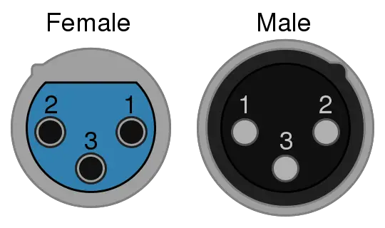
Image from Omegatron and can be found here
The wiring diagram below shows the connections from the table above very clearly.

Image from thebault and can be found here
The next thing is to connect a male XLR connector and a female connector in series with our circuit. This simply means connecting both the male XLR and the female XLR to the output of the MAX485. An important thing to remember is that if this device will be the last one in the chain a 120Ω resistor must be added between the data lines (XLR 2 and XLR 3). This is to reduce signal bounce back, which can create very chaotic scenes if left unchecked.
The RGBW controller
Now that the DMX side of the circuit is sorted, we need a way to control the LED strip. There are countless tutorials on this already but I will include a diagram and short explanation for what is going on.
The diagram

This is where the 10k resistors come in. They are used to keep the FET's gates low until the Arduino sets them high. Many circuits found online omit this part, but if you require the output to only light when the Arduino sends the command to, you will need the resistor. Important! Do not connect the LED strip directly to the Arduino! In most cases, the LED strip will draw far too much current for the Arduino, ESPECIALLY if like me, you are using a pro micro instead of the full-size uno in the diagram! It is important however to connect the grounds of the Arduino and the LED power supply together!
While the pins used in the diagram are not the only pins you can use, it is important to make sure the pins you are using are the PWM pins. If your pins aren't PWM you won't be able to adjust the brightness of each colour and instead, you will only be able to turn them on or off.
In my project, I used one of those cheap car USB chargers to convert the LED strip's 12V power supply to the Arduino's 5V. If you are using the pro micro, note that from my experience anything above 5V will destroy the onboard regulator despite it being rated for up to 12V. If you are going with this approach, make sure to use the RAW input pin to power it to ensure that if something does go wrong, it will at least attempt to regulate the power down to something it can handle.
The Code
The code is a bit of a mix of a few things. It is rather simple though as it is reading data from the serial line and simply sending it back out on the PWM outputs. It uses the DMXSerial library and the source for the sample code I used is also linked.
Note that DMXSerial has special instructions if you are using an Arduino Leonardo (like I was). This is because they have multiple serial UARTS and so you must select which one it must use. If you aren't using a Leonardo you will probably want to go comment out/remove the Serial.begin line because that will most likely interfere with the DMX library.
For reference, here is the DMX reference for the default code as shown here:
| DMX Channel | Function | Values |
| 100 | Red Dimmer | 0-255 Dimmer |
| 101 | Green Dimmer | 0-255 Dimmer |
| 102 | Blue Dimmer | 0-255 Dimmer |
| 103 | White Dimmer | 0-255 Dimmer |
| 104 | Strobe Speed | 0-10 Off, 10-255 : Fast - Slow |
// - - - - -
// DmxSerial - A hardware supported interface to DMX.
// DmxSerialRecv.ino: Sample DMX application for retrieving 3 DMX values:
// address 1 (red) -> PWM Port 9
// address 2 (green) -> PWM Port 6
// address 3 (blue) -> PWM Port 5
//
// Copyright (c) 2011-2015 by Matthias Hertel, http://www.mathertel.de
// This work is licensed under a BSD style license. See http://www.mathertel.de/License.aspx
//
// Documentation and samples are available at http://www.mathertel.de/Arduino
// 25.07.2011 creation of the DmxSerial library.
// 10.09.2011 fully control the serial hardware register
// without using the Arduino Serial (HardwareSerial) class to avoid ISR implementation conflicts.
// 01.12.2011 include file and extension changed to work with the Arduino 1.0 environment
// 28.12.2011 changed to channels 1..3 (RGB) for compatibility with the DmxSerialSend sample.
// 10.05.2012 added some lines to loop to show how to fall back to a default color when no data was received since some time.
// - - - - -

#include

// Constants for demo program

const int RedPin = 5; // PWM output pin for Red Light.
const int GreenPin = 6; // PWM output pin for Green Light.
const int BluePin = 9; // PWM output pin for Blue Light.
const int WhitePin = 10; //PWM output pin for White

int ledState = LOW;
int chan1 = 100;
int chan2 = chan1+1;
int chan3 = chan1+2;
int chan4 = chan1+3;
int chan5 = chan1+4;

unsigned long previousMillis = 0; // will store last time LED was updated
long interval = 20; // interval at which to blink (milliseconds)

boolean strobe = false;

#define RedDefaultLevel 100
#define GreenDefaultLevel 200
#define BlueDefaultLevel 255
#define WhiteDefaultLevel 100

void setup () {
DMXSerial.init(DMXReceiver);

   // set some default values
   DMXSerial.write(1, 80);
   DMXSerial.write(2, 0);
   DMXSerial.write(3, 0);

   // enable pwm outputs
   pinMode(RedPin, OUTPUT); // sets the digital pin as output
   pinMode(GreenPin, OUTPUT);
   pinMode(BluePin, OUTPUT);
   pinMode(WhitePin, OUTPUT);

   Serial.begin(9600);
}


 void loop() {
   // Calculate how long no data backet was received
   unsigned long lastPacket = DMXSerial.noDataSince();
   unsigned long currentMillis = millis();

   if (lastPacket < 5000) {
     // read recent DMX values and set pwm levels
     int strobeSpeed = DMXSerial.read(chan5);
     if (strobeSpeed > 10) {
         strobe = true;
         interval = strobeSpeed-10;
     } else {
         strobe = false;
     }


     if(strobe){
         if (currentMillis - previousMillis >= interval) {
                // save the last time you blinked the LED
                previousMillis = currentMillis;
                // if the LED is off turn it on and vice-versa:
                if (ledState == LOW) {
                     ledState = HIGH;
                     analogWrite(RedPin, DMXSerial.read(chan1));
                     analogWrite(GreenPin, DMXSerial.read(chan2));
                     analogWrite(BluePin, DMXSerial.read(chan3));
                     analogWrite(WhitePin, DMXSerial.read(chan4));
                } else {
                     ledState = LOW;
                     analogWrite(RedPin, 0);
                     analogWrite(GreenPin, 0);
                     analogWrite(BluePin, 0);
                     analogWrite(WhitePin, 0);
                }
         }
     } else {
         analogWrite(RedPin, DMXSerial.read(chan1));
         analogWrite(GreenPin, DMXSerial.read(chan2));
         analogWrite(BluePin, DMXSerial.read(chan3));
         analogWrite(WhitePin, DMXSerial.read(chan4));
     }

   } else {
         // Show pure red color, when no data was received since 5 seconds or more.
        analogWrite(RedPin, RedDefaultLevel);
        analogWrite(GreenPin, GreenDefaultLevel);
        analogWrite(BluePin, BlueDefaultLevel);
        analogWrite(WhitePin, WhiteDefaultLevel);
   }
}


