How to Build a Real Smart Button for Under 10$
Updated on 22nd Sep 2020 18:30 in DIY, Home Assistant, IoT, Tutorial
The idea behind smart buttons is pretty cool, you have a button that you can place anywhere, and pushing it will communicate with a controller that can make anything happen within your home. The problem is that many of these smart buttons also cost an absolute fortune. So today we're going to build a smart internet button ourselves that will cost less than 10$ to build per unit, and possibly even less if you buy all the required materials in bulk to build a few of them!

Disclaimer: This post contains affiliate links. As an Amazon Associate, I earn from qualifying purchases.
Table of Contents
Bill of Materials
- Big 60mm dome push button, on Amazon
- N-Channel signal MOSFET, part number 2n7000 on Amazon
- 3x 10k resistor, this kit contains all the resistors needed on Amazon
- 2x 100k resistor
- 1x 200 ohm resistor
- ESP8266 "ESP-01" type, can be found on Amazon
- A programmer for the ESP, this one comes with an ESP on Amazon
- Some wire, any will do. This set is pretty good on Amazon
- 1x 2 AA battery holder, here is a set of 3 on Amazon
Note about materials
The ESP-01 does not come with a USB plug, unlike the development models often used elsewhere such as the NodeMCU. As such, a programmer is needed. The exact name of the device is a "USB to TTL adapter" - however, if you simply buy a USB to TTL adapter, you will need to manually bridge the GPIO 0 pin to ground when you boot the board. Otherwise, the chip will not enter the mode required for a program to be flashed. This programmer on Amazon has a neat little switch that can be flipped to bridge that pin automatically, I recommend using it for its ease of use.
The MOSFETs are chosen for a reason, it is essential not to use transistors. The reason is that MOSFETs in combination with the very high-value resistors (100k) will draw minimal current when the ESP is sleeping, a requirement for a battery-powered device. During my testing, even the most efficient transistor circuit still used enough current to drain the battery after only a couple of days.
The LED circuit is optional. Quite a few of the listed materials are used to create the circuit for controlling the LED built into the button. Any of those components can be omitted as this device is primarily a button, but the LED adds some lovely feedback that the switch has been activated. The LED comes with the dome buttons anyways, so it is an easy way to take it to the next level.
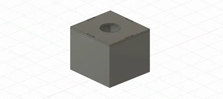
The case
The case is entirely 3D printed and is straightforward to print. If you don't have a 3D printer, the case can probably be made from all sorts of materials, but printing is an excellent way to get the exact dimensions we need for the electronics. I recommend looking at plastic junction boxes if you want a case but don't have a printer, as they are often of a similar size and have lids that can be drilled to fit the button.
The design files can be found here: body, lid. Print with a 10% infill and use whatever speed you like, there aren't too many precise parts so higher speeds will probably work fine. I used generic black PLA, and make sure to use a brim or else the corners will lift.
The circuit
As touched on in the materials section, there is a crucial reason MOSFETs are used here. They do not require much current to activate their gate, which means that the device will not draw much current when it is idle in deep sleep mode.
Unfortunately, the ESP-01 requires GPIO2 to be HIGH at boot, or else it will enter some strange state. It is because of this requirement that we are forced into using inverted logic, sending a LOW on GPIO 2 to cause the LED to come on. Be very careful with the resistor values, I calculated them by simulating different situations and verifying that the voltages of each point in the circuit were correct. Before changing anything, be sure that it won't alter the voltage or the current at the gate of the FETs.
The ESP is a very power-hungry device. It pulls around 70mA when it is doing WiFi transmissions which will not last very long at all on a roughly 2500mA hour AA battery. As a result, we must stop the ESP from using that much power unless it is activated and needs to transmit something. Lucky for us, the ESP supports a deep sleep function that allows it to turn off all the power-intensive components, only drawing a tiny amount of current (~20uA).
Follow the below schematic to build the circuit. The button and LED in the schematic are both parts of the button module, so those can be wired out from your breadboard. The power rail (+3.3V and GND) are where the positive and negative terminals of the battery pack need to connect. Be absolutely sure that the power is connected the right way around as there is no guarantee that things won't quickly burn to a crisp if connected wrong. I also added a switch between the positive battery wire and the circuit so I can quickly turn the power off.

For reference, this is the MOSFET pinout provided by its datasheet:
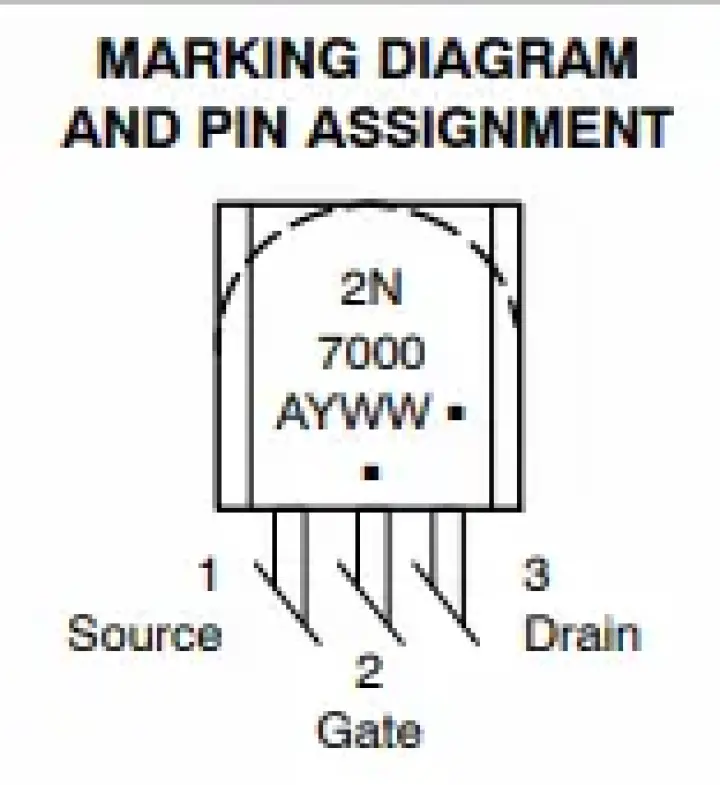
edge to see which
is which
The source will go to ground and the drain to one of the 100k resistors. Here is the same diagram as in the schematic with the outputs annotated:
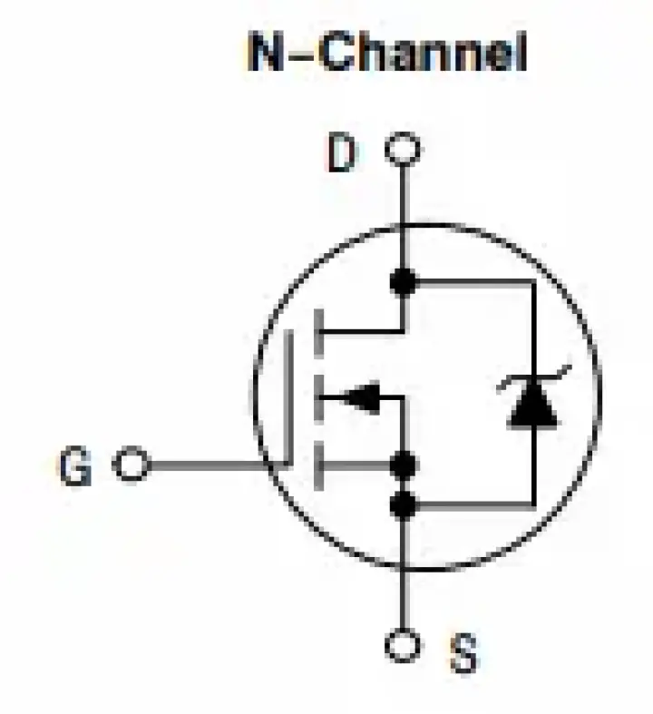
datasheet
I recommend taking a look at the datasheet if you have any doubts about anything relating to the MOSFETs, it is comprehensive and could save you from connecting something wrong, which could damage the components.
The ESP and breadboards
You may have noticed that the ESP-01 does not fit nicely in a breadboard, this is, unfortunately, one of the more difficult problems to deal with. The solution I used is to prototype the circuit using a NodeMCU style of ESP, then to use the actual ESP-01 in the soldered circuit. This won't work if you want to leave it on a breadboard though, so you can also use breakout boards such as these on Amazon. Alternatively, you can also use jumper cables such as these ones on Amazon to connect the ESP pins to the right place on the breadboard.
Soldering
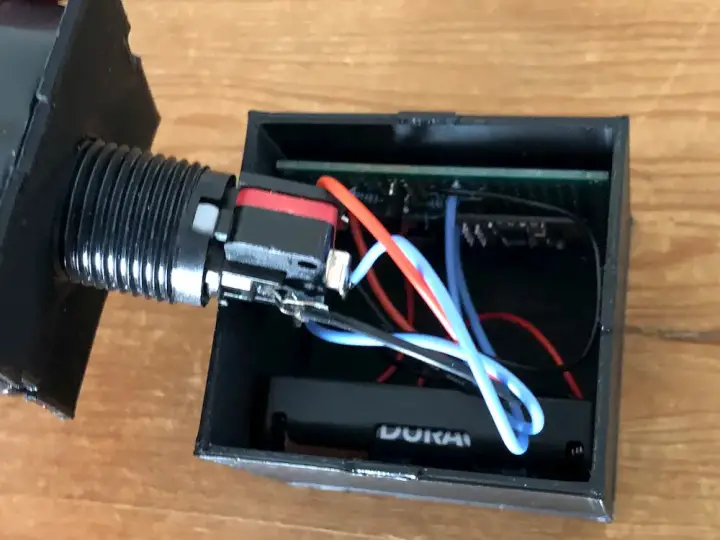
Once you are done with the next sections, and you have verified that everything works well, you can solder all of the components onto a perf-board to make everything more permanent and reduce the chances of something accidentally disconnecting. The case design presented earlier is made with the 60mm by 50mm perf-board, but you might be able to fit other sizes too.
The code
This code seems a bit complicated at first, but there are a few elements that make it seem a lot more complicated than it really is.
Explanation
The first unusual thing is an if statement that checks if the set WiFi SSID is equal to the one we configured at the top of the sketch. This is because we don't have to call WiFi.begin every time, as the ESP will remember the last configured value. As a result, we only call WiFi.begin if the value has changed, and we save time when booting.
We then have some logic for connecting to an MQTT server using the MQTTClient library (Github). The loop() contains some more elements that should be explained. First, the call to client.loop() is responsible for giving the MQTT client the time to do whatever it needs to operate correctly. Next, there is a call to ESP.getResetInfo(). This allows the program to tell the difference between initial power on and waking up from Deep Sleep. As such, the system won't register a button press if you are changing the batteries.
Then some code relates to the LED effect. It merely uses the "effect" array to time each on/off segment of the LED, allowing for some interesting effects to be created, though the one programmed right now is relatively simple. Finally, if the variable "done" is true, we go to sleep, and everything stops executing. When we reset, the code will return to the setup() section, so anything after ESP.deepSleep() will not be called. Of note is that calling sleep with 0 will sleep forever until the device is externally reset - which is what we want.
There is one more aspect of the code that must be explained, the checkForUpdates() code. This code is from the excellent article by Erik Bakke about updating ESPs over the air. The reason we want to have this feature is it will be difficult to access the ESP to flash a new program onto it, especially if it is soldered into the board like mine is. Be sure to read his article if you plan to flash the device over the air. The only change made from the code provided in that article is that the get MAC function uses the MAC address of the WiFi radio to make the resulting MAC address more stable and predictable.
Libraries
Only one extra library is required: MQTTClient. Every other import comes from the ESP8266 core module that is imported when you select the ESP as the board. You can get more information about the MQTTClient library from its Github page.
The code
The code can be seen and copied below. Be sure to change the WIFI_SSID and WIFI_PASS variables, as well as the "fwUrlBase" if you have an HTTP server that will host the firmware files. Change the MQTT_PORT and MQTT_URL to match the port and IP of the MQTT server on your local network. Note: the system will not support DNS names, only IPs. Finally, change the IP address settings to match ones suited for your local network.
#include <ESP8266WiFi.h>
#include <ESP8266HTTPClient.h>
#include <ESP8266httpUpdate.h>
#include <MQTT.h>

#define ledPin 2

#define WIFI_SSID           "ssid"
#define WIFI_PASS           "password"
#define MQTT_PORT           8883
#define MQTT_URL            "192.168.1.50"

const int FW_VERSION = 8;
const char* fwUrlBase = "http://192.168.1.51/fota/"; //the IP of the webserver you will use to perform OTA updates

WiFiClientSecure net;
MQTTClient client;

IPAddress ip(192, 168, 2, 6);
IPAddress gateway(192, 168, 1, 1);
IPAddress subnet(255, 255, 0, 0);

String base_topic = "/sbutton/";

bool done = true;
bool runEffect = false;
bool lastState = LOW;

int effectNext = 0;
int effectState = 0;
int effect[] = {
  500,
  500,
  500,
  500
};

unsigned long previousMillis = 0; //save the last time that we did an LED effect

void setup()
{
  Serial.begin(115200);

  if (WiFi.SSID() != WIFI_SSID) {
    WiFi.config(ip, gateway, subnet);
    WiFi.begin(WIFI_SSID, WIFI_PASS);
    WiFi.persistent(true);
    WiFi.setAutoConnect(true);
    WiFi.setAutoReconnect(true);
  }

  pinMode(ledPin,OUTPUT);
  digitalWrite(ledPin,LOW);

  net.setInsecure();

  // Note: Local domain names (e.g. "Computer.local" on OSX) are not supported by Arduino.
  // You need to set the IP address directly.
  client.begin(MQTT_URL,MQTT_PORT, net);

  Serial.print("\nconnecting...");
  while (!client.connect("smart_button", "try", "try")) {
    Serial.print(".");
    delay(10);
  }

  Serial.println("\nconnected!");

  base_topic.concat(getMAC());


  client.publish(base_topic + "/version", String(FW_VERSION));

  Serial.println("The base MQTT topic is: " + base_topic);
}


void loop()
{
  client.loop();
  String data = ESP.getResetInfo();
  if(data == "Deep-Sleep Wake") {
    //we have been reset, not just plugged in for the first time
    if(!runEffect) { //if run effect is true, then we've already done this - don't do it again!
      client.publish(base_topic, "PUSHED");
      done = false;
      runEffect = true;
      effectState = 0;
    }
  } else if(data == "Power On") {
    checkForUpdates(); //check for firmware updates when the device fully reboots. Powercycling everything will cause this to happen
  }

  if(runEffect) {
    unsigned long currentMillis = millis();
    if(effectState < (sizeof(effect) / sizeof(effect[0]))) {
      if(currentMillis - previousMillis >= effectNext) {
        if(lastState == LOW) {
          lastState = HIGH;
        } else {
          lastState = LOW;
        }

        digitalWrite(ledPin, lastState);
        effectNext = effect[effectState];
        effectState++;
        previousMillis = currentMillis;
        Serial.println(effectState);
      }
    } else {
      //the effect is done, mark everything as completed
      done = true;
    }
  }

  if(done) {
    //we are done, sleep now until the button is pushed
    ESP.deepSleep(0);
  }
}

/*
 * All of the code below is to allow over the air updating of the ESP.
 * As it will be soldered directly into the device, updating will be difficult.
 * This aims to fix that, remove this if you don't want to be able to update
 * over the network
 */
void checkForUpdates() {
  String mac = getMAC();
  String fwURL = String( fwUrlBase );
  fwURL.concat( mac );
  String fwVersionURL = fwURL;
  fwVersionURL.concat( ".version" );

  Serial.println( "Checking for firmware updates." );
  Serial.print( "MAC address: " );
  Serial.println( mac );
  Serial.print( "Firmware version URL: " );
  Serial.println( fwVersionURL );

  HTTPClient httpClient;
  httpClient.begin( fwVersionURL );
  int httpCode = httpClient.GET();
  if( httpCode == 200 ) {
    String newFWVersion = httpClient.getString();

    Serial.print( "Current firmware version: " );
    Serial.println( FW_VERSION );
    Serial.print( "Available firmware version: " );
    Serial.println( newFWVersion );

    int newVersion = newFWVersion.toInt();

    if( newVersion > FW_VERSION ) {
      Serial.println( "Preparing to update" );

      String fwImageURL = fwURL;
      fwImageURL.concat( ".bin" );
      t_httpUpdate_return ret = ESPhttpUpdate.update( fwImageURL );

      switch(ret) {
        case HTTP_UPDATE_FAILED:
          Serial.printf("HTTP_UPDATE_FAILD Error (%d): %s", ESPhttpUpdate.getLastError(), ESPhttpUpdate.getLastErrorString().c_str());
          break;

        case HTTP_UPDATE_NO_UPDATES:
          Serial.println("HTTP_UPDATE_NO_UPDATES");
          break;
      }

      Serial.println("Update done!");
    }
    else {
      Serial.println( "Already on latest version" );
    }
  }
  else {
    Serial.print( "Firmware version check failed, got HTTP response code " );
    Serial.println( httpCode );
  }
  httpClient.end();
}

String getMAC() {

  return WiFi.macAddress();
}
Feel free to remove any part of the code that you won't use. The over the air update is very useful but might not be for everyone. It will work just fine as is even if you don't follow the steps from the article on setting up a webserver. The getMAC() function is required though, so don't remove that. The code will also send the current firmware version to the MQTT topic "/sbutton/<MAC ADDR>/version", so that is an excellent way to see what the current version is.
Flashing the code
To flash the code, use the USB programmer by inserting the ESP-01 into the socket on the back of the device, ensuring it is the right way around. Then open the Arduino IDE, select the correct COM port, and select "Generic ESP8266" as the board. Make sure to select the right board! Now click "Upload" to upload the sketch to the ESP, and if everything goes well, it should work without any errors.
Now open the serial monitor by clicking on the little magnifying glass in the top right corner. Once the monitor opens, you need to power cycle the ESP to cause it to restart. Unplug the programmer, flick the switch into the other position so it will now only communicate instead of trying to flash the ESP. Then plug it back into the computer, ensuring you open the serial monitor as soon as you plug it in.
This might take a few tries, but basically, we want to watch the device boot on the serial monitor. You should see output similar to this:
10:55:58.653 -> ................................................................................................
10:56:00.292 -> connected!
10:56:00.360 -> The base MQTT topic is: /sbutton/48:3F:DA:0C:BC:21
10:56:00.360 -> Checking for firmware updates.
10:56:00.360 -> MAC address: 48:3F:DA:0C:BC:21
10:56:00.360 -> Firmware version URL: http://192.168.1.91/fota/48:3F:DA:0C:BC:21.version
10:56:00.360 -> Current firmware version: 8
10:56:00.394 -> Available firmware version: 6
10:56:00.394 -> Already on latest version
You won't have timestamps if you haven't ticked that box, of course. The critical step at this point is to take note of the base MQTT topic, as this is where the device will publish all of its messages.
Making it do something
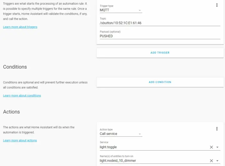
We're going to use Home Assistant to demonstrate how to use it, but as it publishes messages to an MQTT topic, you can use any system that works with MQTT. In Home Assistant, from the Configure->Automations tab, add a new automation using the orange plus button.
Name it whatever you like, add an "MQTT" trigger, then specify the topic found in the "Flashing the code" section. Put "PUSHED" as the payload, as that is the message the device will send when it is activated. Now, as an action, specify whatever. I specified a lamp via a call to the "light.toggle" service. Save the automation, and now when you push the button, the light should toggle on and off! Cool!
Closing thoughts
So that's how to build a cheap smart button. There are many elements of this project that are open to being improved or done differently. This is intended as an example combination of code, circuit, and 3D models. It is made to be tinkered with to achieve the best result for you. What would you use this button for? Did you build one? Let me know in the comments below!


