How to Build a Voice Assistant That Respects Your Privacy
Updated on 6th Jan 2021 16:16 in DIY, Tutorial
There are many different voice assistants available, but they share one common trait that seems so difficult to escape: a required connection to the cloud. Today we are going to build a voice assistant that can work entirely offline, but we will explore setting up your own TTS and STT servers in a future article. For now, we will use the Mycroft servers which claim to respect user privacy by anonymizing every request and requiring an opt-in to their data collection program.
Disclaimer: This post contains affiliate links. As an Amazon Associate, I earn from qualifying purchases.
Table of Contents
Bill of materials
There are a few essentials things to this build, notably a computer to run this on, a microphone array, a speaker and the cables to connect them. Listed here are all the materials required to replicate my design, but obviously, there is room to use different parts as you see fit. Keep in mind that if you plan to 3D print a case like I did, you will need to modify the design to account for these parts.
- a Raspberry Pi 4, or newer. Other versions may work but might be too slow for use
- a case for the Pi, mine came with the screen
- a 3.5inch LCD panel, allows visual information to be displayed. Came with a case
- a small speaker, the case is designed to fit this one
- a suitable microphone array. Check the Mycroft hardware table for guidance on compatible arrays. I recommend the Playstation Eye.
- an "aux" cable, 90 degrees
- a USB C power cable for the Pi
- a USB micro cable, 90 degrees
- an SD card, at least 32GB
As always, be very cautious with the SD card. Inspect the card you receive and be sure it is a real one, as it is prevalent for fakes to be sold, even in legitimate stores.
The speaker I used wasn't super high quality, but as it is primarily used to play voice audio, this wasn't an issue. If you want to use it to play music, it might be worth getting a more expensive speaker to increase the audio quality. For minimal changes, try to find one that has a similar form factor to the VTIN as then it will simply drop into the case as is, without any modifications.
Each 90-degree cable is used to plug into the speaker, which then allows the speaker to lay flat on top of the connectors. Of course, this is only necessary if the speaker connectors are on the rear of the device, but as mine did, this is what I used. The micro USB cable is used to keep the speaker charged, and since the speaker won't be drawing much power unless used continuously, it doesn't need to be anything special.
Notes for future offline use
While we will cover using this device offline in a future guide, there are a few things to keep in mind now if you are going to build this. There is a reason that almost all commercial devices operate with the cloud, and it is because the typical workload of a voice assistant is very processor intensive. Both the work of converting speech to text and text to speech are not easy by any means and are one of the reasons most assistants leverage the cloud.
As explained in How do Smart Assistants Work Under the Hood, the voice assistant uses Text to Speech (TTS) to communicate with you, and Speech to Text (STT) to understand you. Both of the open-source projects we will use in the future are by Mozilla, notably DeepSpeech and Mozilla TTS. They both require a high level of processing power to run things fast enough, however.
As an example, the TTS implementation produces a compelling voice that is much better (in my opinion) than the one that ships with Mycroft. This quality certainly comes at a cost, however, and while running the TTS server without GPU acceleration, it sometimes took as long as 16 seconds for the process to create an audio clip! This amount of time is simply far too long for use in a voice assistant, imagine if it took 16 seconds after all the other processing was done just to respond!
On the other hand, once the program is GPU accelerated using an Nvidia GTX 1080, the time for that same clip is reduced to around 2 seconds, which is even faster than the default TTS Mycroft uses. The point of this note is if you want to use Mycroft offline, be sure to have a pretty beefy computer in the house that can be used to run these applications. The Pi will absolutely not be enough to run anything but the most basic applications, and even then it will probably be very slow.
How to build your voice assistant
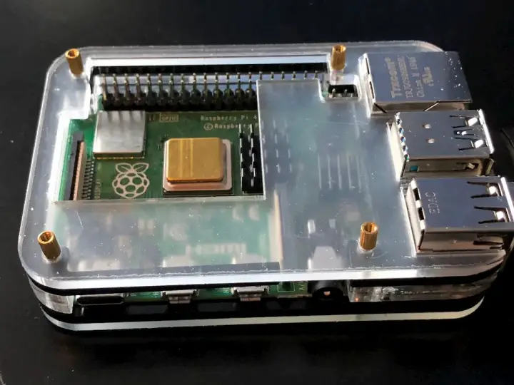
Before installing any software, there are a few steps to follow. The first is to build the case for the Pi. If you used the same case I did, the assembly is pretty straight forwards and involves screwing all of the layers together. Be sure to do this carefully as there is some give for the layers to shift around and become uneven - just double check that each side is perfectly flat before screwing anything in.
This case also includes little heat sinks that are to be placed on specific chips on the board, allowing for better heat dissipation. Don't forget to put these on before screwing in the top layer, as some of the areas you need to access are blocked by this top layer.
Once the case is together, you will have something that looks like this:
The next step is to place the LCD on top of the case, which is a matter of pushing the headers into the Raspberry Pi's GPIO pins. Be sure to carefully follow the instructions as to where the header must push on, as otherwise, it will not function properly (or at all). In my case, the correct location was the furthest pin to the left.
Next, gather the microphone array, the speaker, and all of the cables that they require. In my build, the 90-degree USB micro connector plugs into the power in port on the speaker, while the USB A side plugs into one of the Pi's USB ports. Then the 90-degree aux cable plugs into the "aux" port of the speaker, while the other side plugs into the Pi's audio out port.

Be sure to plug everything that you want to use into the Pi now, as they won't be detected if they aren't plugged in at the time of power on. That should be the microphone array, the aux cable, and a keyboard. Don't plug the power cord in for now, as we will do that once we've got the OS image written to the SD card.
Installing the software
The software we will be using is a new project by KDE called Plasma Bigscreen. It is designed to be used on the Pi to control large televisions while providing voice applications and other typical TV functions. In our case, we aren't using this on a "Bigscreen" at all, but the OS image is still prepared for use in a setup similar to this one and works surprisingly well.
Head over to the Plasma Bigscreen website and download the image. At the time of writing, the project is still in beta, but the image is still very usable. While the image is downloading, make sure you have balenaEtcher installed, and if not go download and install that now. Insert the SD card into the computer, using an adapter if necessary. Then launch balenaEtcher.
Extract the "mycroft-bigscreen-rpi4.img.gz" file to obtain a .img file. Next, in balenaEtcher, select the extracted image as "Flash from file".
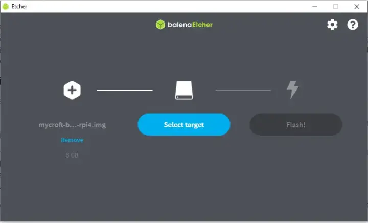
Click the "Select target" button, and choose the SD card from the list.
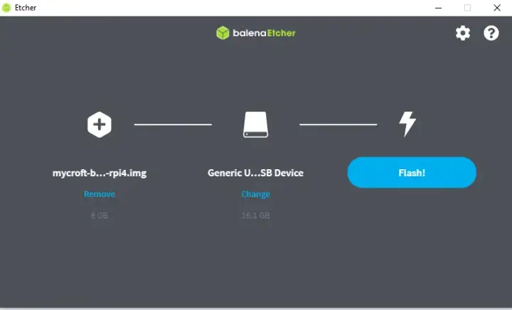
Click the flash button. The program should begin the process of writing the OS image to the SD card. This can take some time, so you might want to do something else while you wait.
Once the SD card has the image on it, remove it from your computer, and place it into the Pi. You should now be ready to boot the Pi.
Configuring the Pi
Be sure to have an HDMI display connected to Pi for this step. Later everything can be done with the onboard display, but at this stage, nothing has been configured and so the external screen is needed. Once a display is connected, plug the power cord into the Pi, and it should begin to boot. You should see a rainbow screen for a short duration, followed by the Bigscreen welcome screen.
Once you are on the home screen, if you opted to connect a mouse, you can simply click on the WiFi icon in the top left to configure the network. Otherwise, hit tab on the keyboard until the WiFi icon is selected, then hit enter to configure the network. There should be a list of all the detected WiFi networks, and you should be able to pick yours from the list. Enter your password, and with any luck, you will now be connected to the internet.
As soon as the device has an internet connection, the Mycroft setup service will start. This will generate a popup that walks you through pairing the device to your home.mycroft.ai account. To do so, simply head over to the devices page of home.mycroft.ai and click on "Add device". You then just need to input the pairing code to have the Pi connect with the backend service. The setup popup should disappear once the pairing process is completed.
Now, we want to find the device's IP address. This can be done via your router, but also with the Pi. To find it on the Pi, hit "ctrl+alt+f2" to switch to a different terminal. You should now see a black screen with a login prompt, for which the default user and password are "mycroft". That is username: "mycroft", password: "mycroft".
You should now have a command-line prompt. Within that prompt, run the following command:
ip addr
The device's IP address should appear on the screen. Write down this address as we will use it in a bit to use ssh for additional configuration.
Configuring the sound settings
Clicking on the little speaker icon in the top right toolbar will open the sound settings of the device. Here it is possible to configure which microphone and speaker will be used. Be sure that the PlayStation Eye is selected, and that the onboard audio output is designated as a speaker. This configuration screen is relatively user friendly and shouldn't prove too troublesome.
Installing the LCD driver
Now, SSH into the Pi using the IP address you found earlier. If you are using Windows, I recommend Putty as a good SSH client but feel free to use anything you like. All of these operations can also be performed directly on the Pi, but SSH is usually easier to manage.
Install the LCD driver for Ubuntu, as described in the manufacturer's instructions:
wget http://www.lcdwiki.com/res/MHS3528/ubuntu-mate-18.04/LCD-show.tar.gztar -xvzf LCD-show.tar.gzchmod -R 755 LCD-showcd LCD-show/sudo ./MHS35-show
The Pi will reboot after that last command runs, but you will notice the display still does not work. This is unfortunate because the script uses the wrong configuration. The problem is easy enough to fix, first head over to the boot partition:
cd /boot
Notice that the Pi's config.txt file has been changed by that script:
nano /boot/config.txt
You will see entries that are from the LCD screen, such as "dtoverlay=mhs35". The problem is that for this OS, the configuration file is located under "/boot/firmware/config.txt", which explains why the script didn't work. To fix this, add the following parameters to that file:
dtparam=i2c_arm=on
#dtparam=i2s=on
dtparam=spi=on
enable_uart=1

dtoverlay=mhs35
Save the file (Ctrl+o, Ctrl+x) and reboot the Pi.
sudo reboot
The LCD display should now show the boot sequence, though you might need to rotate the display. If that is the case, simply add the following to your /boot/firmware/config.txt file:
display_rotate=2
With any luck, at this point you have a Plasma Bigscreen OS installed on your Pi with a functional screen, sound output, and a microphone input. Saying "Hey Mycroft" should result in an audible beep out of the speaker, indicating that it is now listening. Of course, if you've changed the wake word on the Mycroft website, you will need to use that one for this to work.
Building the case
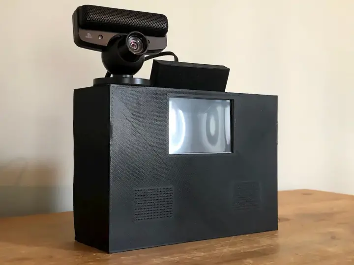
Now is the time to clean up the build and make it look nice. I opted to 3D print an enclosure that would hold all of the components in a suitable spot, while also hiding as many of the wires an internal functions as possible. This design is by no means the best, but it works pretty well and can be a good starting point for anyone looking to model their own case.
The design features a base that has supports for the Pi and the speaker, while also providing inner walls to help reduce movement. The top of the box has two holes, one to run cables in and the other to provide access to the Pi's IO connectors. Next, the lid will be lightly held in place via two spots on each wall. It features a rectangular cut-out for the LCD screen to show through and also includes two grids above the speaker to allow the sound to escape more easily.
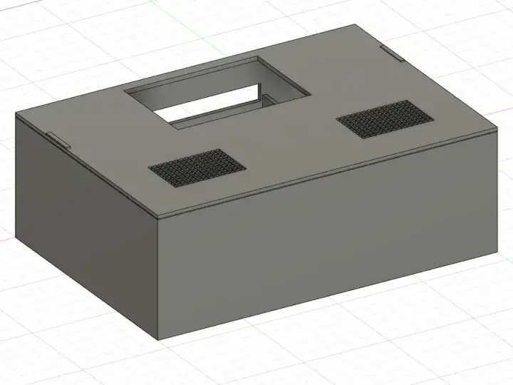
The files are available here: body.stl, lid.stl, and io_cover.stl. Download each one and import them into your favourite slicer to prepare them for printing. I recommend using 10% infill with supports on. Note: the body is a relatively large print, it will take in the order of 10+ hours to print, and as such, it is probably best to print it with a brim at the very least. I experienced very bad warping without, though it will depend on your printer and filament.
All of the parts were printed using cheap black PLA. Assembly of the body is relatively evident, as it merely has a slot for both the Pi and the speaker. The IO cover just fits over the cables coming out of the Pi's IO ports and shields them from view in the front of the device. The cover will likely need some adjustments unless you are using precisely the same cables that I did, the print is tiny and quick, so this shouldn't be a problem.
Placing the components in the case
First, the Pi goes in the upper spot. There are a few supporting walls around the area that the Pi is meant to sit in, and it should hopefully fit snuggly into this spot. The movement should be minimal.
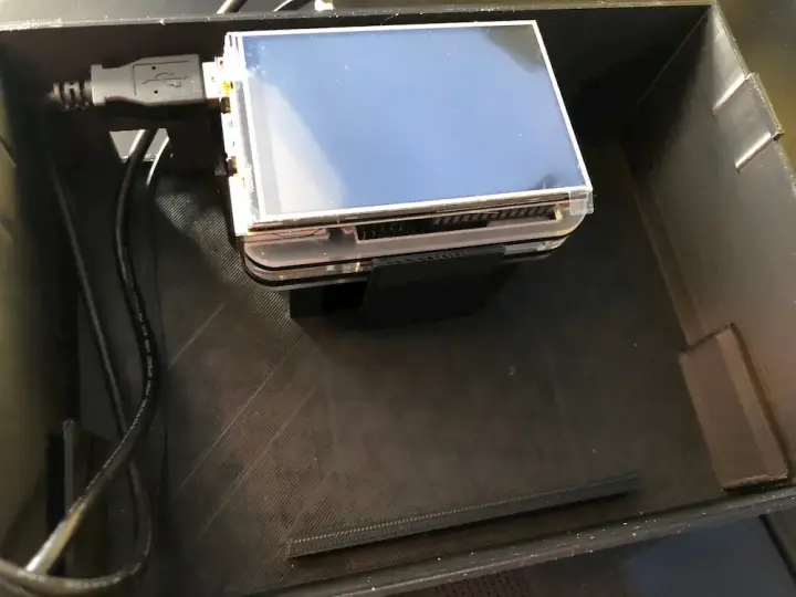
The spot beneath the Pi is where the speaker sits. The side that the sound comes out of is meant to be facing up, or in the same direction as the LCD screen in this configuration. The speaker will sit on its 90-degree cables when you place it in, but remember that when it gets turned over, it is the base of the enclosure that will support its weight. This is one reason that shorter cables are better here, as otherwise trying to organize everything neatly will be quite tricky.
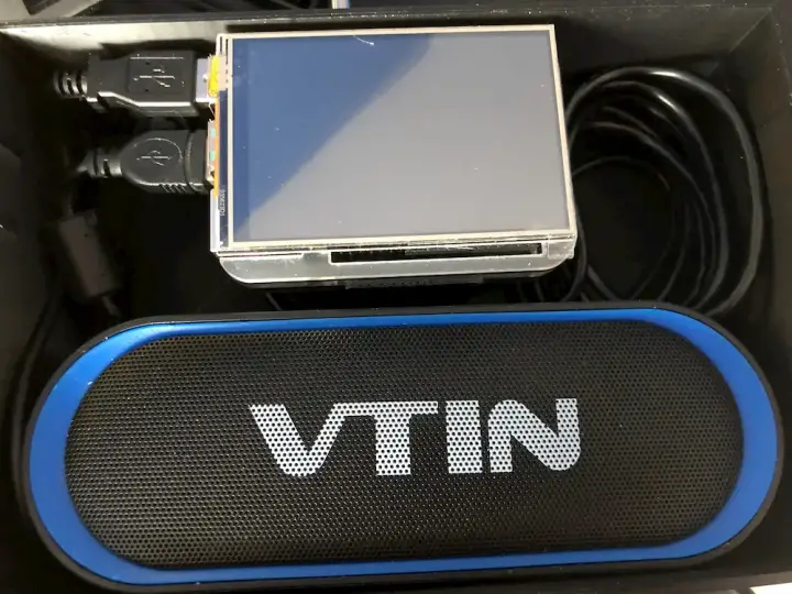
At this stage, you can connect all of the cables and position them neatly into their final resting position. As the Playstation Eye has a very long cord, it may be necessary to coil up the cord in the space to the right of the Pi, as in the picture above. Everything should fit nicely into the enclosure, although the USB connections into the Pi are a bit tight.
Putting the lid on and flipping the box on its side such that the enclosure's cable holes face towards the ceiling will result in the final product. The Eye will sit nicely on top of the box, while the speaker is hidden by the lid. The LCD is accessible both for viewing and touching, allowing the use of the touch screen to operate the device.
Summary
That's it! You now have a voice assistant that is fully capable of running all sorts of tasks such as displaying the time, weather, music, timers, and so much more. One of the advantages of using Plasma Bigscreen instead of Mycroft's own Picroft image is that this image supports Mycroft GUI out of the box. Mycroft GUI is really great for being able to see things instead of just being able to hear them.
Countless skills can be downloaded and used with Mycroft, the Skills Marketplace has a list of all the skills that can be currently installed. Installing a skill is as easy as asking Mycroft to do it, "Hey Mycroft, install count" will install the count skill. You can also write your own skills, should you want to implement a feature that doesn't exist yet.
Click here to see the next part of this guide where we make this run offline!


