How to Build a DIY RGB Wall For Cheap With ColorWall
Updated on 8th Feb 2021 23:39 in DIY, General, Home Assistant, Tutorial
LED strips have become a popular option for decorating a room as they can create a vastly different ambience with the press of a button. While strips are awesome, they aren't always the most practical thing as they can be difficult to mount in the right way for your application. To make things easier, some companies sell light panels which are easy to mount directly on the wall. They can change color and offer tons of effects to keep things interesting. The most common product in this space is perhaps the "Nanoleaf light panel" which does the job perfectly, albeit a bit expensively. To save some money and get additional personalization, I built my own light panels in a project I call ColorWall.
Disclaimer: This post contains affiliate links. As an Amazon Associate, I earn from qualifying purchases.
Table of Contents
Introduction
There is nothing wrong with commercial options, and they are actually a better choice for most people. The biggest problem with them is that they can get expensive quickly with each panel easily costing over 20$ each. This DIY project manages to create each one for around 14$, which is a big difference when you need many of them. You can lower the cost simply by using less expensive LED strips as they represent around 80% of the cost. An easy way to find a cheaper strip is to pick one with a lower density than the one I used as the lowest ones often cost half the price. The downside is that each LED will be clearly visible, and the light won't be diffused properly.
You can almost certainly find a cheaper source of strips, but the key is that they must be WS2811 LED (or similar) else the project may not work. These can be individually addressed, allowing for animated effects and complex color blending. Each panel is 3D printed out of transparent PETG filament and can immediately be used without any other assembly. Most other DIY panels use acrylic, which is great for this purpose but is difficult to use and work with. An overwhelming amount of this project's complexity comes from the software I'm providing as a download for free. If you enjoy these kinds of projects, be sure to share my post as it really does help!
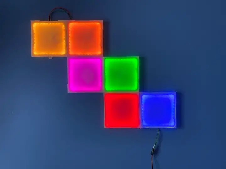
The final product
This is a short video demonstrating what we are going to be building in this post. While I have provided a few effects out of the box, you can add more and tweak the project as you see fit.
Materials
These materials may be substituted for others with varying rates of success. I have personally used and tested the following, so using different ones will be at your own risk. I can't possibly plan for every combination of every material, so please stay close to the original plan to avoid having to modify any software.
Electronics
- 1x-4x WS2811 LED strips 100 pixels/m, such as these on Amazon. Higher is better so if there aren't any 100/m models available use something higher like 144/m. One meter can usually make around 2 panels.
- 1x 5V 5A Power Supply, such as this one on Amazon. You will need more amps if you want to use more LEDs! More on this later.
- 1x 18-20 AWG Wire, such as this one on Amazon. I used this, but please be very careful to get wire that will handle the current drawn by your panels. More LEDs = more Amps.
- 1x 5A fuse (or lower/higher, depending on your wire) to prevent fires, such as these on Amazon. While the project will work without this, I highly recommend using one as the fuse will burn before any damage is done to your house.
Controller
- 1x PNP transistor, such as these on Amazon.
- 1x ESP8266 NodeMCU, such as these on Amazon.
- 1x 1k resistor, such as the one in this kit on Amazon.
- 1x 2.2k resistor, from the same kit as above.
- 1x 5cm x 7cm perfboard, such as the one in this kit on Amazon.
Cases
- 1x 1kg reel of transparent PETG, such as this one on Amazon. I used this, but different kinds will give different effects. Make sure you use PETG though! Other common materials aren't as transparent and have a lower heat tolerance.
- 1x roll of heavy-duty double-sided tape, such as this one on Amazon. Whichever type you use, it needs to be really strong to hold the panels on the wall.
Considerations
High density LED strips need to be used. Otherwise, the LEDs will create hot spots that will ruin the effect. Don't be like me, I accidentally bought loads of 60 pixel/m strips and only realized when I installed them and noticed they looked wrong. The visual difference is astonishing - always use the highest density you can to avoid this problem! Keep in mind that the higher pixel count will increase the total current draw, which requires lower gauge wire and a stronger power supply.
The reel of PETG will last a really long time to the extent that I had plenty left over after printing 6 panels along with all the failed prototypes (there's a lot). The controller is actually identical to the one I built in this article, but the schematic is duplicated here for convenience. Wire gauge is important! You need to know how many panels you plan to use to get the right wire thickness. An insufficiently thick wire could melt or even start a fire, so make sure you get that part right!
Most manufacturers recommend injecting power every so many LEDs to counteract the voltage drop that occurs on the other end of the strip. This is also a good way to manage a large number of panels without needing ultra-thick wiring everywhere. If you use multiple power supplies, be sure to connect the grounds together, or weird things could happen. It might be a better idea to use a single power supply and have several thick wires inject power at several locations further down the strip. None of this is in the scope of this article though, so be sure to do your research!

While this project is visually stunning and can save quite a lot of money, be diligent when wiring the panels to avoid a situation where too much current could start a fire. If you aren't sure how thick the wires should be, check with someone who does as these things can be dangerous.
Tools
There are a few tools needed to build this project. The most critical piece is the 3D printer as everything revolves around the cheap, easy to print panel design. To see which tools I use and recommend, be sure to check out my recommended tools here.
Required
- 3D printer - any will do but printing PETG absolutely requires a heated bed and apparently works best with a glass bed (which is what I use).
- Soldering iron with solder - anything works
- Wire/plastic cutters
- Multimeter
The best part about this project is that minimal tools are required, although printing the panels can take some time.
The panels
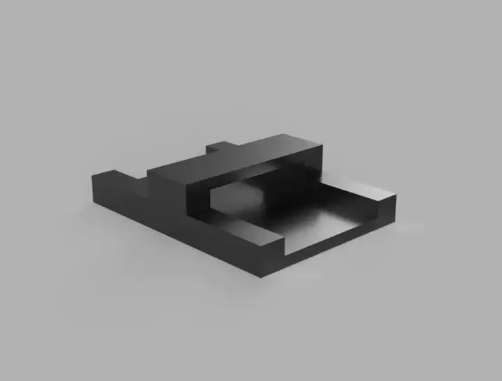
Each panel is designed with restrictive constraints in place, so there is not much extra space. The thickness was carefully considered such that it wouldn't stick out too far from the wall while still having enough space for both the strips and the wires. Every panel needs to have a way to connect to another panel in all directions to allow customization, which is why there is a hole on each side. The hole needs to have enough clearance so that the wires have room to go under the strips. The top of the panel has four elevated sections used to hold the lid once pushed on. A small ridge exists around the entire length of the panel to make routing wires easier in the spot where the ends of the strips meet.
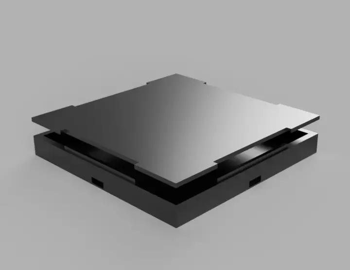
Finally, the lid is designed to simply push into the base without too much trouble. To make connecting panels a bit easier, a connector design also exists and is made to push into the slot on both panels. They are purposely slightly wider than the slot they fit in so that they are mechanically held in once pushed together - though it should not be relied upon to keep everything together. A panel consists of both the body and the lid which must be printed separately unless you have a large printer bed.
Printing tips
3D printing isn't always easy, and this design is no exception. After many failed prototypes, I eventually came up with a few tricks to get the best results when printing this model. You may need to adjust them or use your own settings to get the best print!
- Use 10% infill and adjust the nozzle temperature to around 230°C with a bed temperature of 85°C
- If you've never printed PETG, it's slightly different, and sometimes it needs to be closer to the bed than other filaments. Cura has a slicer setting to change the Z height - I set it to -0.05mm.
- Always print with a brim! You have certainly seen people print models directly without any adhesion technique, but I assure you that these models will experience problems without one. Corner lift and bad first layer adhesion are just some of the problems you could have, so use a brim!
- Use Gyroid Infill for lids. The lid is special in that it must diffuse the light around to create a good effect. Typical infill patterns will be evident and can distract from the diffusion. The gyroid is also more likely to print well with PETG, making everything look better on the finished product.
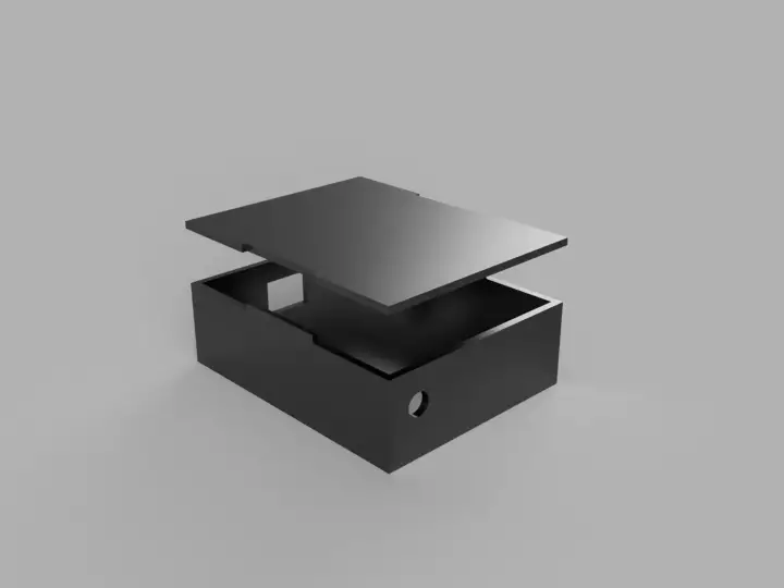
Controller case
The controller also needs a case, and it obviously has different requirements - the biggest one being that we don't need anything transparent anymore! I printed the controller case with white PLA at 10% gyroid infill with a brim. You can probably crank up the speed because the defaults are really slow, especially for a print like this that doesn't have tiny details. Other than that, I didn't change anything from the default PLA profile in Cura, so it should work fine. The case is not a complex design, and the most difficult part of it was lining up the DC barrel jack with the hole in the side.
You might need to play with either the model's settings or cleverly pack everything into the box depending on your specific dimensions. The most likely difference will be with the board's height as it's mostly determined by how long the pins on the bottom are. Mine is the lowest it can be without cutting the NodeMCU pins off, so ensure nothing sticks out further than that for the best results. The only other thing to consider is the hole for the wires as it must be wide enough for a typical light connector. You probably don't want to leave the connector out in the open, so I pushed it into the little box to keep things tidy.
CAD model download
Download each model here. Some models have a body and a lid while others only have one file. Once downloaded, import the STL files into your slicer and prepare them for your printer as usual. See the earlier section on each model for specific printing settings and instructions. I used Cura to slice all of the models, and some needed extra work before sending to the printer. The connector can be copied to print 10 copies in a single go by multiplying the model in the slicer.
Click on the links below to download the specified model.
Panel
Controller
Controller Lid, Controller Body
Connector
Things to print
To build this project, be sure to print one controller body and lid, the number of panels you want (body and lid), and a bunch of connectors. This will certainly take a while, so it's best to get started on it right away. Be sure to use transparent filament for the panels (both lid and body) or they will look weird. I printed the controller's case with white PLA, but you can use whatever you like as it's more about aesthetics than function. The connectors are necessary to reduce the strain on the wires as they mechanically hold two panels together (albeit quite weakly). They are tiny and print quite quickly, so print tons so you won't run out while working on the next part!
Electronics
The controller's circuit is surprisingly simple and actually only uses around 5 components thanks to the fancy processing the LEDs are doing. In fact, the wonderful thing about WS8211 LEDs is that they manage themselves completely and only require a single wire to control a lot of them. That means that we can control all aspects of each LED on the strip with a single transistor. While that makes the hardware easy to build, you can imagine that the software will become quite complex and that's exactly what has happened. Despite the additional complexity, the benefits of this approach far outweigh the drawbacks.

Due to the potentially high current, the system will deal with, I highly recommend soldering all of the components into a small 50x70mm perfboard to keep things secure. You may be wondering why we don't make the circuit even simpler by connecting the output pin directly to the LED strip rather than via a transistor. The answer is two-fold: first, the ESP runs on 3.3V logic while the LED strips are expecting 5V and second, the current provided by the output pin may not be enough.
You could get away with running the strip directly from the ESP's output, but you will likely run into problems with the voltage drop or potentially destroying the processor in a worst-case scenario. The controller is actually the most complicated part of the build with the rest being simple wiring. Once built, you'll just need to solder wires to each LED strip segment so you can connect them in any way you like, starting with the controller's output.
Once you've built the controller, it can be placed into its case as there won't be any more changes. The case has a hole for both the light connector and the DC barrel jack. Make sure these things are lined up, and you will be good to go. I tucked the cables and other extra stuff into the box so they would be hidden from sight unless the box was opened.

Important note
While unlikely for most situations, high current can melt the wires between your LED strips if you aren't careful. I mentioned the wire gauge earlier, and the reality is that you must use the lowest gauge you can that will still fit between the panels. The LED specifications should tell you how much current you will be dealing with. In my case, the 100 LED/m strip has a rated wattage of 0.3W if the LED is emitting all 3 colors (the worst-case scenario). For that worst-case, we then have 42 LEDs per panel and 6 panels in total, so 0.3W * 42 (LEDs per panel) * 6 (panels) = 75.6W.
To get the current in amps from that, we can use the formula I = P / V, where P is the wattage and V is the voltage. As such, we find that we need 15.12A in the worst-case scenario. That's really high! Unfortunately, things are actually much more complicated than this, and when I measured the real current draw, it was around 2A. There are many reasons for this, and it could be any one of them alone or all of them together, causing this difference. In any case, a big problem is the voltage drop created by the resistance of the wire, which reduces the voltage at the end of the strip.
When I measured the voltage on the other side of my strip, I found that my initial 5V was down to around 3V. The result is that each LED will use a varying amount of current, making our previous calculation invalid and difficult to do correctly. That's why you must measure the current yourself to determine how thick the wires should be. I also recommend putting a 5A fuse between the controller and the LED strips to reduce the chances of a destructive overload.
How thick should the wires be?
Calculating the required wire thickness is not always trivial because many factors come into play. The biggest problem you're going to run into is your wire's thermal capacity being exceeded, resulting in a fire. When too much current runs through a wire, the conductor heats up until it gets so hot the insulation begins to melt. Once the insulation melts, serious damage or fire both become a real concern. The important thing to remember is that a given wire has a maximum number of amps that can be safely pulled and that exceeding that is really bad.
Things get more complicated when we consider that the wire's length is important in determining the voltage drop. Wires have some resistance, which increases with their length, causing the voltage to drop on the other end. While the voltage doesn't directly affect the current, lower voltages can cause your load (LEDs in this case) to behave differently. If the voltage at the other end of my LED strip was below 3V, the chances are that those LEDs simply wouldn't light or would be really dim. It can also cause the current draw to be lower as the load isn't receiving its ideal voltage.
Using an American Wire Gauge table on Wikipedia, we find that a standard 22 AWG can handle around 7A at an absolute maximum before reaching 75°C. As you may imagine, the exact point your wire will reach that temperature will vary depending on if the wires are run through open air or if they are in a tightly wrapped bundle. Regardless, you will want to use wire that can handle much more than the current you are drawing to have some headroom. I measured my circuit using around 2A in the worst case, meaning the 22 AWG wire will work just fine. Remember you can only know for sure by measuring it yourself! Check the operating temperature using a thermal camera to be sure you aren't overloading anything.
Preparing the LED strips
While the panels are printing, there are a few things to do before mounting the strips inside each panel. The first step is to cut the strips at the same interval so they can be controlled as panels. Important: do not vary the number of LEDs from panel to panel - they must be the same! I used an interval of 42 LEDs for my panels as they fit in the case nicely and provided nice light coverage, but this will depend on pixel density. I recommend doing a test fit before installing them in the panel permanently by placing the lid on top to confirm that it works. Check everything works with one panel before cutting all of the strips, or you will create a lot of pain for yourself.
The following images use strips with the incorrect LED density. I took the pictures while I was using the wrong ones, so keep in mind that yours will have more LEDs than these!

Once you've cut a segment, the next step is to solder wires to the inputs and outputs so we can link each panel to the next. There is no specific way to do this so just make sure that the wires you are soldering are of equal length and reach out of any of the ports. I made my "out" wires a few centimetres longer than the input wires so that each output wire will meet the next panel's input wire inside the next panel. Use the thickest wire that will fit through the ports so you can handle higher amounts of current as this will limit future expansion. Strip the ends of each wire so you can twist them together with the wires on the other side when you connect the panels together.
Soldering tip: make sure you "tin" both sides of what you are going to solder before attempting to solder them. In this case, you would put some solder on the pad of the LED strip and some on the wire. This way, when you connect them together, they already have solder to stick to each other with. You can add a bit more as needed to make the connection more secure.
Repeat for each strip you are going to make - keep in mind you need one per panel!

Wiring the panels
Once the panels have been printed, it's time to wire the LED strips into them. Using the LED strips, we soldered from the previous step, carefully place them into a panel so that the light will shine into the centre. You will have a bit of a struggle with the ends that have wires soldered to them because they need to cross each other to be in their final position. For now, you can just tuck one side's wire under the other to keep it out of the way. It's important that none of these wires block the adjacent LEDs or you will have weird shadows show up when the panel lights up.
When you are satisfied that everything fits nicely, insert a connector into each port so you won't accidentally block them with the strip (I did this the first few times, it's a pain to fix). Ensure the strip is not sticking out of the top as they will prevent the lid from fitting on properly. Finally, carefully route the wires under the other end of the strip so that neither of them are in the way of any nearby LEDs. This can be annoying, so just do your best to get them out of the way. Once you are happy that everything is positioned right, carefully peel off the sticker on the back of the strip to attach them to the side of your panel.

At this point, you should have a finished panel! Repeat this for each panel you want to make, and you will be done preparing the panels for their final wiring. This last step is where you get to make a cool shape or pattern out of your panels. Position them how you like then simply connect all the wires together to turn individual panels into a color wall. To connect a panel with another, simply twist the "out" wires on one panel to the "in" wires on the other, taping them down inside the "in" panel once you're done. Be sure to pull the wires through a connector piece to keep everything tidy and reduce the strain on the wires.

Repeat this process for each panel and create any shape you like. I made a sort of staircase, but you can be more creative if you like by making something crazier. With enough panels, you could design almost anything, and it will certainly look awesome! In the next step, we will upload the firmware to the controller to test that our connections are good. Once everything works, we will put the whole assembly on the wall.
The firmware
The firmware is written in C++ and uses the Arduino library to make things easier. I used the Sloeber IDE to program everything as it became too complex to do in the standard Arduino IDE, but you can still use it to upload the code. In fact, unless you plan on making significant modifications, the regular IDE will do just fine for changing the settings and uploading the program to your ESP. There are a few things to change before you upload the code though, with most of them located in a file named "UserSettings.h".
Download the sketch from the ColorWall firmware repository here, unzip it, and open it in the Arduino IDE by clicking on "ColorWall.ino". Check the list of required libraries in the comment at the top of the main file and make sure to use the "Sketch->Include library" menu to add any of the required libraries. You will get compilation errors if you do not do this! If a required library isn't available, install it using "Sketch->Library Manager" using the search bar. Once installed, you should be able to include it using the previous technique.
You should see a tab named "UserSettings.h" in the top bar of the Arduino IDE. Click it to begin configuring. I have included the mentioned file below for completeness, but you should already have it in the sketch.
/*
 * UserSettings.h
 *
 *  Created on: Jan. 24, 2021
 *      Author: raphael
 */

#ifndef USERSETTINGS_H_
#define USERSETTINGS_H_

#include
#include

// LED settings
#define DATA_PIN    4
//#define CLK_PIN   4
#define LED_TYPE    WS2811
#define COLOR_ORDER GRB

//Strip/panel settings
#define NUM_LEDS    252
#define NUM_PANELS 6
#define NUM_LEDS_PER_PANEL 42

//The draw rate, do not change unless you know what you are doing!
#define DRAW_DELAY   20

static const char *ssid =  "your_wifi";     // replace with your wifi ssid and wpa2 key
static const char *pass =  "your_password";
const IPAddress ip(192, 168, 1, 6);  //the IP address of the device
const IPAddress gateway(192, 168, 1, 1); //the gateway
const IPAddress subnet(255, 255, 255, 0); //the subnet

#endif /* USERSETTINGS_H_ */
There are a few settings to change here, most notably the data pin on the NodeMCU you are using to control the LEDs, the type of LEDs, and the color order. My strip was a WS2812B, so I set "LED_TYPE" to "WS2812B". Color order is important and will be listed on the LED strip's product page/datasheet - mine was GRB (NOT RGB!). Here are the other settings.
- "NUM_LEDS" should be the total number of LEDs in your project (LEDs per panel * number of panels)
- "NUM_PANELS" should be the total number of panels, mine was 6
- "NUM_LEDS_PER_PANEL" should be the number of LEDs per panel, mine was 42
- "ssid" should be your WiFi network
- "pass" should be your WiFi password
- "ip" should be the IP of the device (you can pick)
- "gateway" should be the IP address of your gateway (usually your router)
- "subnet" is your subnet mask, usually "255.255.255.0"
Don't forget to set an IP address you will remember, and that isn't currently used by anything on your network. Once all of those are configured, you are ready to go! Plug a USB cable into your board and into the computer, select the right port from the "Tools->Board" menu and hit "upload". Once the sketch is uploaded, the controller should reboot, connect to the WiFi, and start an effect on your LED strips. If you don't see an effect, check for any errors in your configuration. If everything is correct, you can open the serial monitor, set it to 115200 bauds and reset the board to see if any errors appear. Otherwise, recheck your connections.
Everything is now controllable over WiFi using a REST API provided by the controller. Making an HTTP POST request to the "/power" endpoint will cause the LEDs to either turn on or off, along with setting the master brightness. Making the same request but with a GET will fetch the LEDs' current state, allowing you to see what's happening without being there. Controlling everything like this would be annoying, which is why it's actually meant for other programs to issue commands. There could be a mobile app that offers direct control or anything else really. I choose to write a Home Assistant integration as that implicitly covers remote control from anywhere, including a mobile app.
ColorWall Home Assistant Integration
Surprisingly, most of my time on this project was spent here, trying to write the perfect integration to control ColorWall hardware. Compared to what you've already done, this part is a walk in the park as the integration will walk you through the configuration and initial setup.
Installation
There are two installation options: HACS or manually. If you've never heard of HACS, you should skip to the manual method. HACS makes installing custom components really easy so it may be worth considering if you do this a lot.
Installing via HACS
To install using HACS, go to the HACS menu in Home Assistant.

Next, click on "Integrations" and click on the three dots in the top left corner. Select "Custom Repositories". From there, paste the ColorWall-Hass repository https://github.com/woder/colorwall-hass into the "Add repository" field in the bottom. The entire URL must be put into the field, or it won't work. Select "Integration" under "Category" then click the add button.

Now type "ColorWall" into the search bar at the top and click "Install" when the repository you just added appears.
Installing manually
To install manually, navigate to the ColorWall-Hass repository here and download everything. Now unzip the repo and copy the "color_wall" directory from "/custom_components/". Paste the directory into your Home Assistant "custom_components" directory ensuring the path remains the same as it was in the zip file. You should now have a "color_wall" folder inside Home Assistant's custom_components directory.
Setting up the integration
After installing the integration with either method, restart Home Assistant. Now head over to the "Configure" menu in Home Assistant and click on "Integrations". On the integrations page, click "Add integration" on the bottom right and search "ColorWall" in the popup window.

Click on the result of your search and enter the IP address of the controller you set in the previous step. Then click "Submit" to configure the integration.

Using ColorWall Home Assistant
When configured, the integration will add one entity for the controller and one entity for each panel. I recommend you add these to a group on your Home Assistant dashboard for easier control. Below is a picture of the UI I use.

To obtain this look, I used a "Vertical Stack card configuration" with both a "Light" card and an "Entities" card. The configuration is as follows.

On page 2, an entity group is used to put all individual panels in one place.

The entire setup can then be controlled using the top card for brightness, on/off, or effect selection. Individual panel configuration can be done with the controls below. The main entity also has the effect field, allowing you to change the current effect by choosing from a list.

Each panel also offers a few basic settings when clicked on, including brightness, color, and power.

Panels use their assigned color for certain effects, in addition to their solid color state. If you were to build a second controller for use in Home Assistant, you would just need to add the integration again and specify the new device's IP. New entities will be added with a different name to differentiate them.
Features
The integration supports all of the firmware features and integrates them tightly with Home Assistant. Panels can be used in automation, scripts and whatever you like! Keep in mind there is a small delay between performing the action and the update of each panel as they are separate entities that all need to update.
Some supported features include:
- Master brightness control
- Master power control
- Effect selection
- Individual panel brightness
- Individual panel color selection
- Individual panel power control
The code is on my Github, so feel free to add more if these features don't support your use case.
Configuring effects
Effects can be configured by going to the integration page in Home Assistant and clicking "Options" on the ColorWall card. Here, you can configure either a single effect or all of them at once.

From the first menu, select the effect you want to configure or pick "All" if you want to change them all. A new form will appear with the configurable fields, allowing you to change any of them as you see fit. The first field of every form exists to display the name of the effect you are currently configuring, so do not edit it!

Once you click "Submit", the values will immediately be changed, and you should see the effect behaving differently. Each effect has settings that can be configured which are not always the same as other effects. For example, the settings for "Smooth" are very different from the ones for "Bpm".
Note: if you selected "Configure all effects", you will need to click "Submit" on every form displayed for the changes to save.
Mounting to the wall
Once all the panels are connected together, you will probably have them all laid out on the table. I recommend keeping them there until everything is tested and working properly. Fixing problems becomes significantly more difficult one the panels are attached to the wall, so it's best to do that last. When you are satisfied that everything works well, you can mount them to the wall using heavy-duty double-sided tape.
I started by flipping the entire panel assembly over on the table so that the rear of each panel was facing up. Then, I carefully cut strips of double-sided tape the same length as a panel's width, and I stuck them to the back of each one. Once every panel was taped, I carefully lifted the entire assembly and stuck it to the wall, pressing hard on each panel to get good adhesion. You may need help for this step as the panels are not firmly connected to each other, making it difficult to move them as one without any falling. I used one other person's help to hold one side while I held the other to keep everything straight while we stuck it to the wall.

Once everything was mounted, the panels were securely stuck to the wall with the wires coming out of either end. To clean everything up, tuck the unused wires from the other side into the last panel and tape the exposed metal to prevent shorts. Solder or twist the wires leading from the controller to the first panel and tape it flush with the wall. Place the controller nearby and connect everything together.

Conclusion
Overall, this has been quite the project to work on. Nothing was simple, and nothing was easy, but the end result is quite satisfying. I encourage everyone to post their setup in the comments below. Found a bug? Let me know on Github. I've tried to fix everything before publishing this article, but we all know its impossible to fix it all.
Please be responsible with this information. The current taken by some parts of this project can be enough to melt wires and cause a fire, so make sure you only power it on while you are there. I also have made every effort to ensure everything is safe and will not cause fires, destroy property, or shock anyone. Despite my efforts, sometimes problems can occur while replicating a project and its important to understand that you are responsible for your project's safety.


