How to Build an RGB LED Strip Controller Easily
Updated on 31st Jan 2021 16:43 in DIY, Home Assistant, Tutorial
Colour-changing RGB strips are fun! While there is nothing wrong with buying a commercial kit, I found that they were quite expensive for what I wanted to do. Here we are going to use WS2812B LEDs in a strip to achieve individually addressable RGB lighting. All that just means that we can tell any LED on the strip to do something different than the rest, which is really cool for effects! Let's see how to build our own controller so we can control them from Home Assistant!
Disclaimer: This post contains affiliate links. As an Amazon Associate, I earn from qualifying purchases.
Bill of materials
- 1x PNP transistor, such as this one on Amazon
- 1x ESP8266, such as the NodeMCU on Amazon
- 1x 1k resistor, like the ones from this kit on Amazon
- 1x 2.2k resistor
- 1x suitable power supply, such as this one on Amazon
- some wire
- a WS2812B LED strip (5v), such as this one on Amazon
Notes about materials
There are a few things to keep in mind, but it's mostly focused on the different parts you can use. Almost everything in the list of materials can be substituted for something equivalent, so keep that in mind!
The power supply
The power supply is a bit tricky, it will depend a lot on what you are planning on doing. Power requirements go up as more strips are added, but even within the same brand, there are differences in the strips. The LED density is specified on each strip and will affect the power draw. Use the product page to understand how much current each strip uses, keeping in mind ones with more LEDs are going to use more. Multiply the required power of each strip by the number of strips, and you have the size of your power supply! As an example, if I had two 1 meter strips that both use 5A, I would need a 10A power supply.
Unfortunately, nothing is ever that easy. The manufacturer of my particular strips indicates that an additional power supply is required every 16ft, to keep the voltage consistent along the entire length of the rails. Otherwise, the LEDs at the end of the strip could receive less voltage than they need, resulting in them malfunctioning. If you are planning on chaining a lot of strips together, you should consider using the 12v version as they need less current. In my case, the product page said I needed a 5v 6A power supply to work. I couldn't find any of those though, so I ended up using a 5v 5A, and it seems to work well enough.
The ESP
I used a NodeMCU style of ESP, but you can use any ESP8266 you like. The only thing to remember is that some versions do not regulate the incoming power, so you won't be able to power them from the same power supply as the strip. You will also need to ensure the ESP gets the correct voltage of 3.3v using a step-down converter. Otherwise, everything is the same for each board, just be sure to identify GPIO2 and follow along once you sort out the power delivery.
The LED strip
For this guide, we are going to use the WS2812B type of LED strip. These are different from the typical RGB or RGBW kind because they only have one control wire instead of 3 or more. Rather than controlling the brightness of each colour individually, these LEDs have logic inside of them. Normally, you can create any mix of color you like by changing the brightness of each color on the strip, the controller then uses the wire that is connected to that color to make the change. The logic in these allows you to control each one individually, which is pretty cool! They are a lot easier to build a controller for since they don't need MOSFETs to perform the switching of the high current.
Building it
You may know that the ESP operates on 3.3v. That's fine, and all, but our strips are expecting a 5v control signal (or 12v if you are using the 12v version). This problem is easily dealt with by using a transistor to switch the control wire of the LED high or low, instead of driving it directly with the GPIO pin. The following schematic shows how to build the circuit:

It is actually quite simple. One of the nice things about addressable LEDs is that we don't need much circuitry to control them, unlike the more basic kind that need each color switched. The transistor plays a critical role in providing the LEDs with a control signal of the right voltage. We use a PNP transistor circuit instead of the more common NPN option because this formation is non-inverting, meaning we only need one instead of two. This reduces the number of support components required and allows us to give the strips the correct voltage. They might work when connected directly to the pin, but it's not wise to do so.
In terms of the GPIO pins, there is some evidence that GPIO2 is a better choice in situations like these. The reason is that that pin is backed by a hardware UART, allowing it to handle generating very complex pulses. Using some of the other pins causes the work to be done in software which is much slower and will lead to problems when using many strips together. We don't need to worry about interfering with the UART because GPIO2 is connected to UART2, which is not the one used by the USB connector on the NodeMCU.
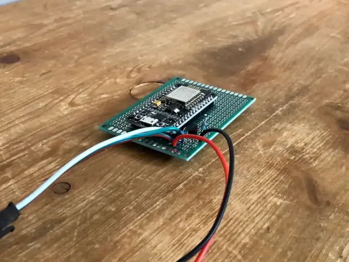
When you get all the parts together, build it on a breadboard first to ensure everything is going to work. Once the circuit is built, do the next steps while it's still on the breadboard and once everything is done, solder it into perf board. Obviously, you can leave it on a breadboard, but I recommend soldering things in securely when the circuit involves higher current, as is the case here.
The software
To make things nice and easy, we're going to use Tasmota to control our strip. Tasmota is open-source firmware written to provide more features along with better control of smart devices built with ESP8266s. A lot of cheap smart home products are built using the ESP, so a common technique is to flash this firmware onto the device to use it with Home Assistant or other controllers. We're going to take advantage of this to have an easy way of setting it up, but you can always write your own code! There are plenty of libraries available for controlling WS2812B LEDs, and you can program several different effects.
Flashing Tasmota onto the device
The first step is to download Tasmota. There will be another way to do this later, but it's good to know where the firmware you are installing comes from. Head over to the Tasmota Github repo's releases page and download the latest release. The file is called tasmota.bin, it will be at the bottom of each release (after all of the notes). Next, download Tasmotizer, a program designed to flash the firmware image onto ESPs easily. Again use the release page on the Github to download the latest release. Be sure to download the right one for your platform, .exe for windows, source for everyone else.
Once downloaded, run the program. You should see a screen like below:
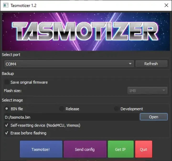
Now you can select your firmware image from wherever you saved it using the browse button, or you can click on "Release" and select the "tasmota.bin" file from there. Next, make sure your ESP is plugged into the computer and refresh the ports list.
Select the port it's connected to. For me, it was COM4. Once you are sure the settings are correct, click "Tasmotize!" and watch as the software does the rest. By clicking on "Send config", you can configure your WiFi network and your MQTT server.
Important: if you use TLS on your MQTT server, you will need to compile Tasmota from source for it to work. As my MQTT server uses TLS, I had to compile it from source. It isn't that difficult to do, but it's out of the scope of this guide. The page on the Tasmota website about compiling is a good resource, along with the page about enabling the TLS features.
Once you flash the config, the device should be connected to your WiFi and to your MQTT server. Click on "Get IP" to find the IP of the device:
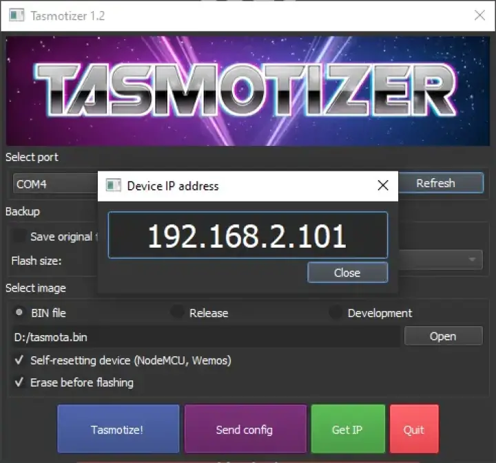
Put that IP into a browser, and you will see the Tasmota web panel. Click on "Configuration", then "Configure Module". Now select "Generic Module", and put in the following settings: D4 GPIO2: 07 WS2812.
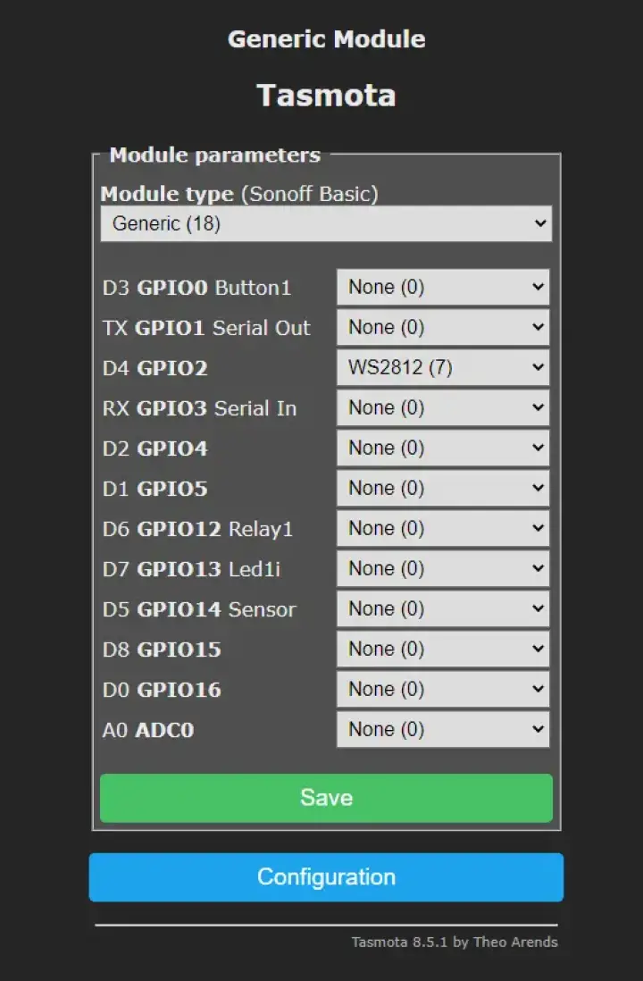
Save the config, and the ESP will restart. Once everything comes back, the main Tasmota page should have a color picker allowing you to change the color of the strip along with a button to toggle it on and off.
Important: Click on the "Console" button in the main menu. From there you should see a screen like below. In the input box, type "pixels <number of LEDs>", replacing the number with the actual number of LEDs in your strip. In my case, I had 60 LEDs, so I typed "pixels 60". If you do not do this, it will not work properly!

At this point, playing with the color picker on the main menu should work well. If it does, congratulations! If it doesn't, double-check everything we've done so far and make sure you followed all the steps correctly, Ensure that the circuit is built correctly as well!
Configuring Home Assistant
This part isn't obvious out of the box, but it is rather simple. The first step is to make sure you have Home Assistant connected to your MQTT server. In some cases, the MQTT server might be running as an addon. Whatever your situation is, be sure you have it connected before the next part. Now we can configure the device. At the time of writing, there is still no way to add MQTT devices via the UI, so we must do it using the configuration.yaml file.
Head into your config file and find the light platform. Under that, you want to put the following config:
- platform: mqtt
  name: "Addressable LED"
  command_topic: "cmnd/tasmota_0CBC21/POWER"
  state_topic: "stat/tasmota_0CBC21/RESULT"
  state_value_template: "{{ value_json.POWER }}"
  availability_topic: "tele/tasmota_0CBC21/LWT"
  brightness_command_topic: "cmnd/tasmota_0CBC21/Dimmer"
  brightness_state_topic: "stat/tasmota_0CBC21/RESULT"
  brightness_scale: 100
  on_command_type: "brightness"
  brightness_value_template: "{{ value_json.Dimmer }}"
  rgb_command_topic: "cmnd/tasmota_0CBC21/Color2"
  rgb_state_topic: "stat/tasmota_0CBC21/RESULT"
  rgb_value_template: "{{ value_json.Color.split(',')[0:3]|join(',') }}"
  effect_command_topic: "cmnd/tasmota_0CBC21/Scheme"
  effect_state_topic: "stat/tasmota_0CBC21/RESULT"
  effect_value_template: "{{ value_json.Scheme }}"
  effect_list:
    - 0
    - 1
    - 2
    - 3
    - 4
    - 5
    - 6
    - 7
    - 8
    - 9
    - 10
    - 11
    - 12
  payload_on: "ON"
  payload_off: "OFF"
  payload_available: "Online"
  payload_not_available: "Offline"
  qos: 1
  retain: false
The only thing you need to change to make it work with your setup is the name of each topic. My Tasmota device is called "tasmota_0CBC21", so that's why each topic has that string in it. Just change each one for the name of your specific device before adding it into your config. The Tasmota web console will display the name of the device when it boots up as it connects to the WiFi network. Once that's done, restart Home Assistant. When it comes back, you should see the new entity in the list. If you are using the customized UI, you need to edit it and add the new device before it will show up.
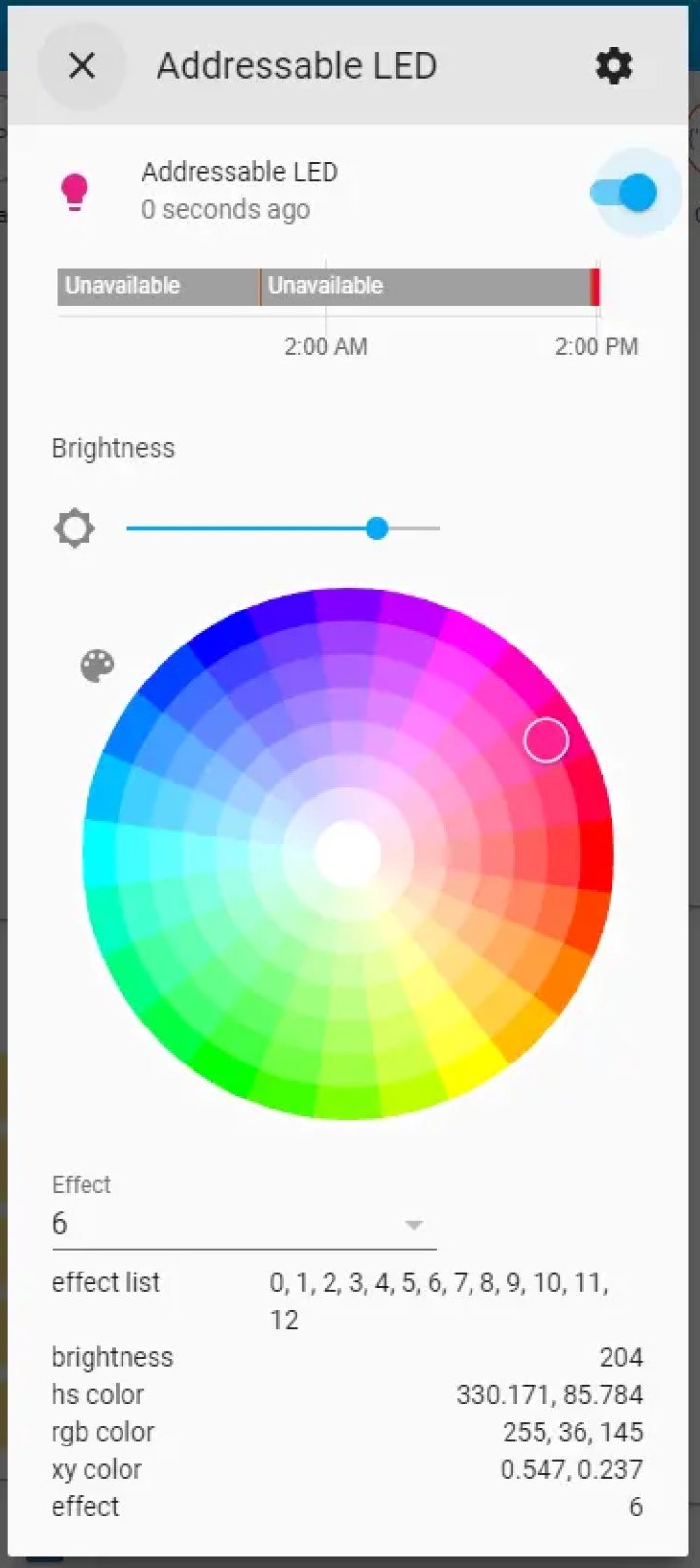
Once you turn the strip on in Home Assistant, a bunch of controls will appear. Here you can pick the color of the LEDs, the brightness, along with the effect. Picking an effect from the dropdown list will cause the strip to perform the given action. The ones above 5 are special and only work on the addressable LEDs. Check this page on the Tasmota website to see all the different options.


